What is Laser Beam Profiler?
Table of Contents
- 1. Measurement of beam pattern
- 1.1. What is Laser Beam Profiler?
- 1.2. Definition of beam diameter
- 1.2.1. Details of beam diameter
- 1.3. Beam pattern measurement with a camera-based Laser Beam Profiler
- 1.4. Beam pattern measurement with a scanning-based Laser Beam Profiler
- 1.4.1. Pinhole Profiler
- 1.4.2. Slit Profilers
- 1.4.3. Knife-edge Profilers
- 1.5. Measurement of NFP (Near Field Pattern) and FFP (Far Field Pattern)
- 2. Measurement of beam quality
- 3. Glossary
- 3.1. Cover glass
- 3.2. What is CCD?
- 3.3. What is rame rate
- 3.4. What is ensor size
- 3.5. What is bit number
- 3.6. What is trigger
1. Measurement of beam pattern
1.1 What is Laser Beam Profiler?
Laser Beam Profiler are a device that measures the beam diameter and spatial intensity distribution of a laser beam. They are characteristics of a laser beam, which means the laser beam behavior.
For example, the condensing characteristics of a laser with the same intensity and beam diameter are changed by the different spatial intensity distribution, which can’t obtain the same behavior. Moreover, the strictly designed laser resonator is also difficult to accurately predict the beam characteristics obtained due to the surrounding environment such as manufacturing errors of the optical elements and the temperature.
Therefore, measurement of the beam characteristics is important in an application using a laser beam, so Laser Beam Profiler are available for the measurement.
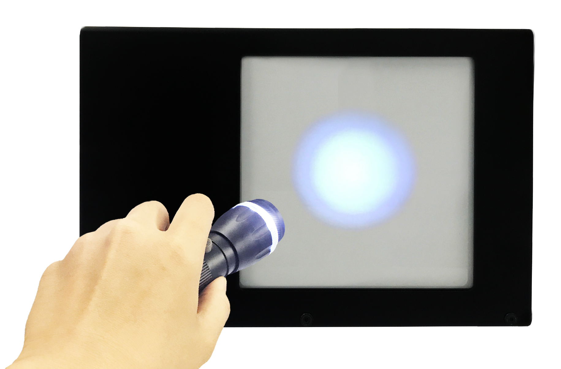
There are mainly 2 measuring methods: camera-based type and scanning-based type (Figure 1).
The camera-based Laser Beam Profiler measures the entire beam at one time with a 2D optical sensor, so it can measure the beam pattern efficiently. In addition, it can measure continuous-wave lasers and pulsed lasers.
The scanning-based Laser Beam Profiler sequentially measures the laser beam intensity using a single photodetector. The profiler is more reasonable than the camera-based one, and it can measure the pattern of continuous-wave lasers. Both methods can measure the NFP (near field pattern) and F.F.P. (far field pattern) of the beam.
We will describe the definition of the beam diameter and each beam profile measuring method here.
(Figure: Advantages & Disadvantages of Camera-based Laser Beam Profiler and Scanning-based Laser Beam Profiler )
| Advantages | Disadvantages | |
|---|---|---|
| Camera-based Laser Beam Profiler ・CCD camera |
・Short measuring time ・Available for measuring pulsed lasers ・Available for distinguishing complex beam patterns (flat-top or doughnut)) |
・Expensive ・Unavailable for measuring small beam diameter *Kokyo’s Laser Beam Profiler can easily measure small beam diameter at a reasonable price ・Unavailable for measuring large beam diameter *Kokyo’s Laser Beam Profiler can easily measure large beam diameter at a reasonable price ) |
| Scanning-based Laser Beam Profiler ・Pinhole ・Slit ・Knife-edge |
・Easy to measure small beam diameter | ・Long measuring time ・Unavailable for measuring pulsed lasers ・Unavailable for distinguishing complex beam patterns |
1.2 Definition of beam diameter
The laser beam has a light intensity distribution in a plane orthogonal to the propagation direction. Beam light has no clear boundary, so its beam diameter is necessary to be defined. There are several definitions for beam diameter; the most common definition is 1/e2 as the maximum light intensity. It is described by a Gaussian beam, a centrosymmetric intensity distribution. The intensity distribution of a Gaussian beam with light intensity is expressed by the following equation.
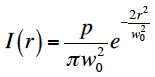
Figure1(a) shows a profile and an intensity profile of a Gaussian beam represented by the above equation. The beam diameter is W0. In addition to this definition, the full width at half maximum (full-width half-maximum, FWHM) is also commonly used.
The above definition cannot be easily applied to an asymmetric beam pattern. For a beam with a complex pattern, a range including 86.5% of the total light intensity (Fig. 1 (b)) [1] is defined as a beam diameter. The ISO standards define the level at which the value of the second moment of intensity distribution is 1/e2 as the beam diameter. More complex beam patterns and difficult-to-define beam diameter follow the standard.
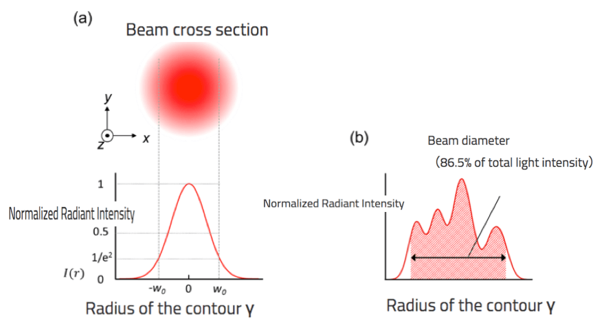
Table 1 Definition of the beam diameter)
(a) Gaussian beam
(b) Beam with complex patterns)
1.2.1. Details of beam diameter
1.3 Beam pattern measurement with a camera-based Laser Beam Profiler
1.3.1 CCD camera-based Laser Beam Profiler
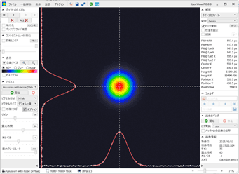
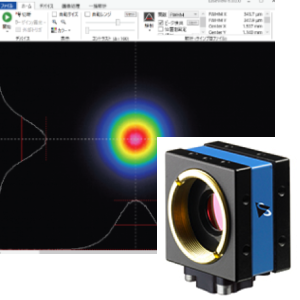
To detect beam light, a semiconductor device called a charged coupled device (CCD) is available. It arranges the optical sensor in a two-dimensional array. When the light is irradiated onto the CCD, its intensity distribution is recorded pixel by pixel. The obtained intensity information is fetched in a computer as digital data and then reconstructed as a two-dimensional or three-dimensional intensity distribution image via software. (Fig. 2)The spatial resolution is determined by the pixel size of the CCD. The typical pixel size is approximately 10 mm, so a beam diameter from 100 μm to 10 μm is measurable.
As the reading speed of the charge stored in the CCD is faster, the measurement time can be faster. However, it is limited by the monitor frame rate (30 ~ 60 fps) and the data transfer rate from the CCD to the PC.
A semiconductor laser can’t directly measure a beam profile of 1.3 μm or 1.5 μm used in optical communication because the typical CCD detects a wavelength of about 1.1 μm. For the out-of-band wavelength, an image converter for converting infrared light into visible light and a pyroelectric image sensor is used.
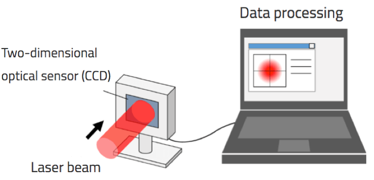
Figure 2 CCD camera-based Laser Beam Profiler
1.4 Beam pattern measurement with a scanning-based Laser Beam Profiler
The scanning-based Laser Beam Profiler has the following characteristics: it measures the intensity of a beam light passing through a shield such as a pinhole or a slit in a plane orthogonal to the optical axis. Measuring the light intensity while scanning the shield along with its cross-section measures the spatial intensity distribution of the beam light. It takes more time than the camera-based one but allows a convenient measurement. In addition to that, attenuation of the laser beam is not necessarily required. With a photodetector that matches the wavelengths for measurement, any wavelength beams can be measured. We describe the details of each method below.
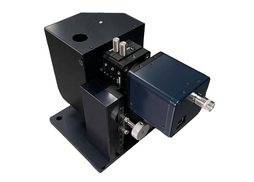
1.4.1 Pinhole Profiler
The pinhole profiler obtains the intensity distribution of the entire beam by two-dimensionally scanning the pinhole in a plane orthogonal to the optical axis of the laser beam (Fig 3). Reducing the pinhole diameter can easily enhance the spatial resolution. A pinhole having a size of about 1% of the beam diameter is generally used. The profiler can measure both the intensity distribution of an arbitrary beam shape and complex beam patterns, which is available for the measurement of continuous-wave lasers without time fluctuation.
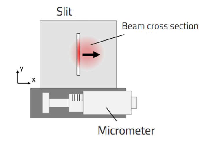
Fig 4 Slit Profiler
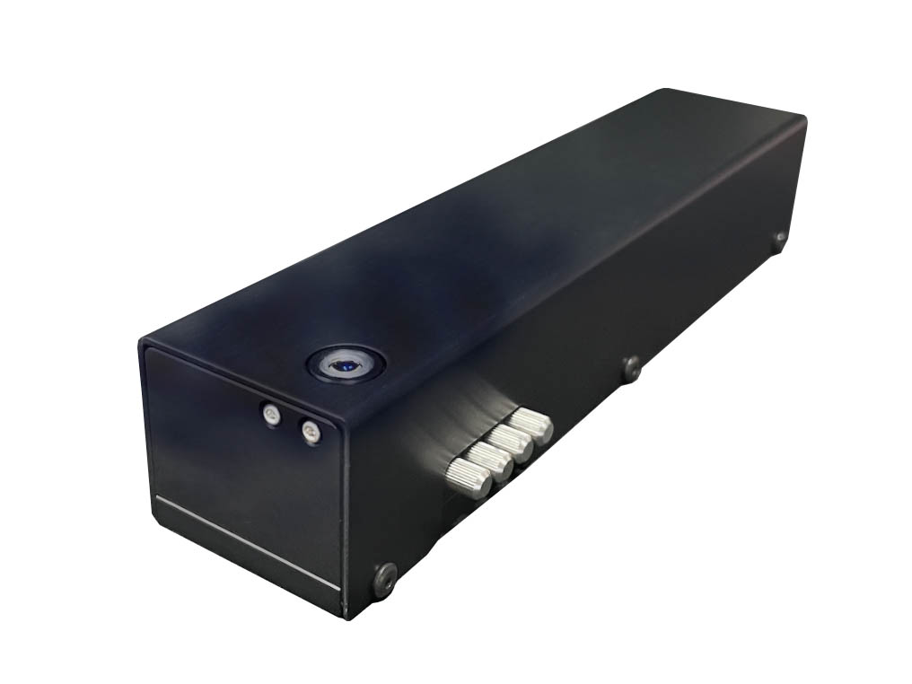
1.4.2 Slit Profilers
Like the pinhole profiler, the slit profiler measures the spatial intensity distribution by scanning a slit with a rectangular hole in the beam profile to measure the intensity of passing light through the slit (Fig. 4). One‐dimensional intensity distribution along the scanning direction can be obtained. Scanning from multiple directions can acquire an intensity distribution of two or more dimensions. The profiler is suitable for the measurement of beams with axially symmetric intensity distribution. Narrowing the slit width can enhance the spatial resolution: 0.2μm spatial resolution can measure about 20 μm of the beam diameter.
Fig 4 Slit Profiler
1.4.3 Knife-edge Profilers
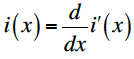
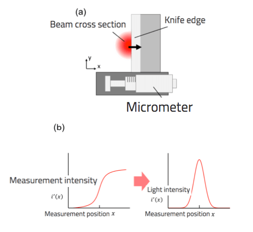
Fig 5 (a) Knife-edge profiler, (b) Relationship between intensity in measurement and intensity distribution
1.5 Measurement of NFP (Near Field Pattern) and FFP (Far Field Pattern)
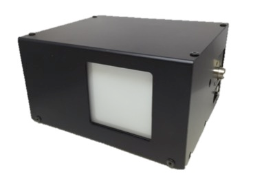
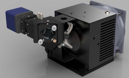
Measurement of a beam profile near an output end (NFP: near field pattern) and a beam profile sufficiently far from the output end (FFP: far field pattern) is necessary to understand the characteristics of beams from photoelectric devices such as semiconductor lasers and light fibers. We describe how camera-based Laser Beam Profiler (CCD method) measure these beam profiles. For measuring the micron-level spatial intensity distribution (NFP: Near Field Patterns) at the output end, optical zoom systems like a microscope are available (Fig. 6). An objective lens enhances the output end, while a relay lens forms an image on a CCD. It must form an accurate image for a very small beam. That can be easily solved by a beam splitter, which divides the beam into two and introduces one beam into a CCD for monitoring, positioning it for forming images with a wider field of view.
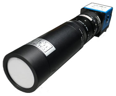
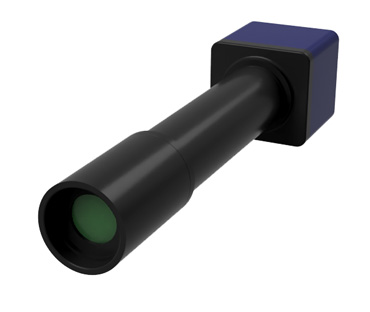
The measurement of the diffusion angle of semiconductor lasers and the numerical aperture (NA) of light fibers is possible by the FFP measurement. For the measurement, an optical system using an f-θ lens that converts the incidence angle to the focal position is available (Fig. 7).
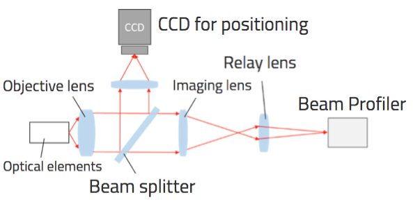
Fig 6 Optical system for NFP measurement
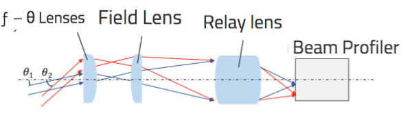
Fig. 7 F.F.P. measurement optical system
2. Measurement of Beam Quality
2.1 What is M2 Beam Quality Measurement System
The beam quality measurement system is a device for measuring laser beam quality. The condensing characteristics of laser beams change depending on the characteristics of the output beam. This is an important parameter in the laser processing field where a certain quality is required. The condensing characteristics of the beam are defined as M2, K, and BPP (beam parameter product) as indicators of the beam quality. A condensed laser beam by a lens determines its theoretical minimum spot diameter by the diffraction limit. However, the disturbing beam intensity profile limits the beam to the diffraction limit. M2 indicates how many times the condensed beam diameter becomes than that of the diffraction limit. If M2 is 1, the beam theoretically obtains the minimum condensed spot. The K is the reciprocal of M2. BPP is expressed by the product of the beam waist radius and the beam divergence angle like M2. BPP mainly indicates the beam quality of semiconductor lasers.
2.2 Definition of M2
Beam with a strong directivity and near-straight propagation such as a laser beam increases the beam diameter gradually as it propagates. Fig 8 shows the propagating beam near the beam waist. Near the beam waist, the beam radii wx, y (z) in the x-axis and y-axis directions are given by the following equation [3].
![]()
w0x, 0y, z0x, 0y, θ0x, 0y represent the beam waist radius, beam waist position, and beam divergence in the x-axis and y-axis. M2x and y are introduced as parameters for determining the beam quality in each axis and have the following properties.
- M2 must be greater than or equal to 1.
- In M2 ≡ 1, the beam is a single-mode Gaussian beam.
- The value of M2 indicates how many times the condensed beam diameter becomes than that of the diffraction limit.)
M2 is defined as follows using the parameters of the laser beam.
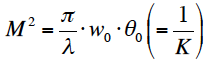
λ shows the wavelengh of laser light.
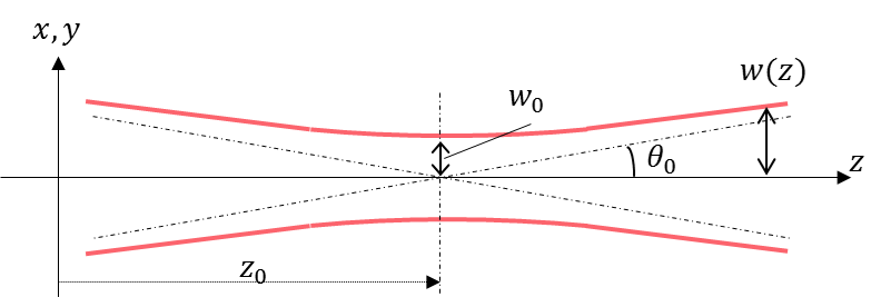
Fig 8 Near the beam waist of Centrosymmetric Gaussian beam
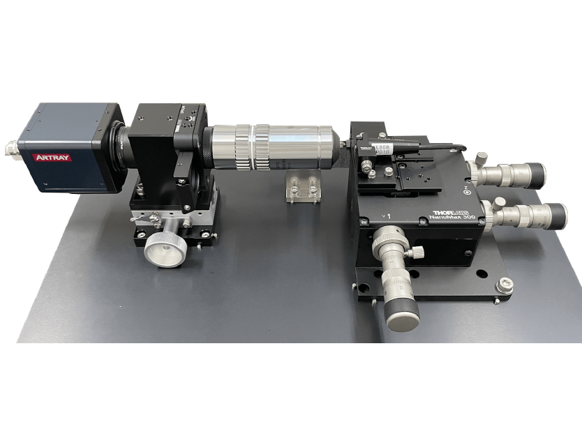
2.3 Measurement of M2
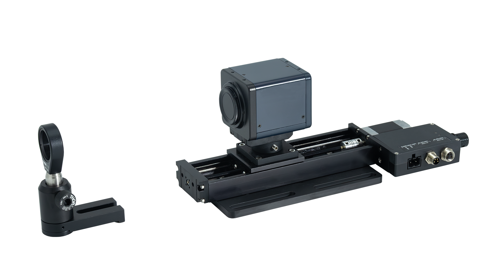
As shown above, M2 can be determined by measuring the beam waist radius and the beam divergence. These parameters are obtained by focusing the beam to measure the beam diameter at several points along its optical axis (Fig 9). Measurement at more points is desirable for the reduction of errors. More accurately beam waist position is obtained by taking many measurement points, especially near the beam waist. The M2 of main laser beams is summarized in Table 2 [4].
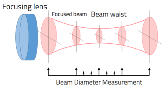
Fig 9 Measurement of M2
Table Major Laser Beam Quality
| Light sources | M2 |
|---|---|
| He-Ne Laser | < 1.1 |
| Ion Laser | 1.1 ~ 1.3 |
| Semiconductor Laser (Collimated light, TEM00) | 1.1 ~ 1.7 |
| High Power Multi-Mode Laser | 3 ~ 4 |
3. Glossary
3.1 Cover glass
On the other hand, for picosecond and femtosecond lasers, we can recommend both cameras with and without cover glass. As a simple rule of thumb, if the coherence length is shorter than the distance between the CCD element and the cover glass (about 1-2 mm), interference will not occur. For example, pulses with a Fourier transform limit of less than 1 ps will rarely cause interference fringes.
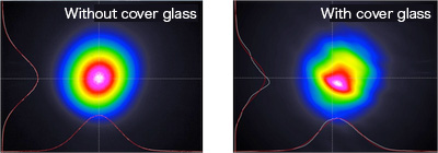 Fig. Beam profile collapse with cover glass (right).
When a laser beam is focused by a lens and used for processing, even if the laser has the same performance (e.g., 1W, 1mJ), the focusing characteristics will change depending on the quality of the ejected beam, and as a result, the processing characteristics will change.
In order to predict the processing characteristics, it is necessary to measure the beam quality.
What is CCD?
A CCD (Charged Coupled Device) is a charge-coupled device that consists of an array of photosensitive areas and transfer areas made of semiconductors. By determining the position in the CCD where the semiconductor receives light, the image of the object to be photographed (in this case, a laser) can be obtained. Resolution is a factor that indicates the fineness and smoothness of the image. The higher the resolution, the more natural the image quality. The resolution shown in the table above refers to the number of photosensitive areas in the CCD. A high resolution means a large number of photosensitive areas. For example, a resolution of 1628 x 1236 indicates that there are about 2 million photosensitive areas arranged in the CCD.
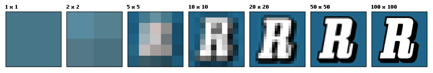
Fig. Difference in resolution
Reference:Wikipedia
What is frame rate ?
Video is created by stitching together still images. The frame rate (fps) indicates how many images are stitched together in one second. The higher the frame rate, the smoother the video will be.
The frame rate can be 60 fps, 50 fps, 30 fps, 25 fps, 24 fps, etc. 60 fps means that 60 frames are recorded per second.
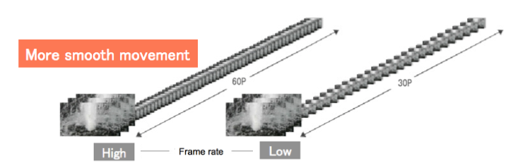
Fig. Difference in smoothness by frame rate
Reference:Nikon
What is sensor size ?
This indicates the size of the CCD sensor. The larger the CCD, the larger the size of each light-receiving element, and thus the more light can be captured. In other words, for the same resolution (number of pixels), the larger the sensor size, the better the image quality.
What is bit number?
The bit number refers to the number of steps used to divide the tones from black to white. 8 bits means 2 to the 8th power, so 256 steps, or 4096 steps for 12 bits. The larger the number of bits, the more beautifully the gradation is expressed.
What is trigger?
A trigger is a function that uses an input signal as a switch to start imaging. By applying a voltage to the CCD camera as a trigger at the same time as the laser irradiation, the observation can be synchronized with the laser irradiation. In the case of pulsed waves, it is difficult to manually turn the imaging on and off according to the pulse, so the trigger is generally used for observation.