Frequency Pulling Effect — What It Is
YS-307 achieves frequency stabilization by leveraging the frequency pulling effect caused by the anomalous dispersion of the laser gain medium.
Because the control signal is in the frequency domain and the oscillation mode can be stabilized at the center of the Ne gain curve, the stabilization based on frequency pulling enables:
- Frequency stability of 10-11 over a wide range of averaging times (from 1 s to 1,000 s)
- 3 mW single-mode output
- ±300 kHz resettability (frequency reproducibility after power cycling)
Principle of the Frequency Pulling Effect
The frequency pulling phenomenon occurs when the oscillation mode inside the Ne gain curve is slightly pulled toward the center of the gain curve from the cavity phase condition mode position νm, resulting in an actual oscillation frequency ν (Fig. 1(a)).
The pulling amount ν − νm depends on the shape of the Ne gain curve and varies with the mode position νm (Fig. 1(b)). When multiple longitudinal modes exist, the beat frequency between modes changes with their oscillation positions. We extract this change as a control signal and perform stabilization.
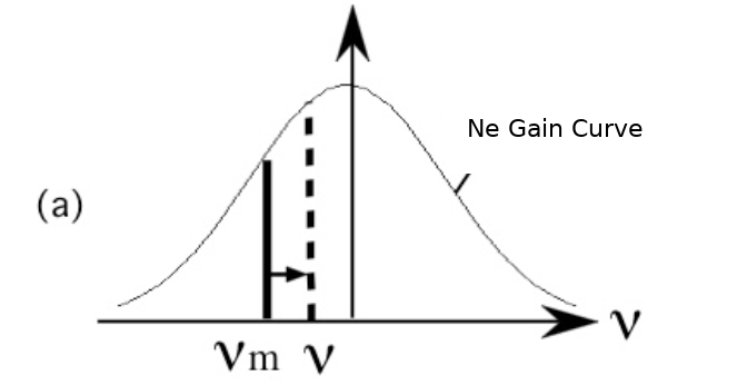
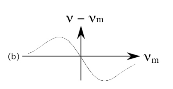
Fig. 1 Frequency Pulling Effect
Stabilization Utilizing the Frequency Pulling Effect (YS-307)
Overview of the stabilization control
Following the YS-307 system configuration (Fig. 2):
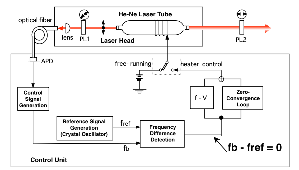
- Changes in beat frequency between multiple modes produced by frequency pulling are extracted and used as the control signal.
- The P and S polarizations in the back beam are combined by the polarizer (PL1), coupled into an optical fiber, and detected by an avalanche photodiode (APD) inside the controller.
- The APD converts variations due to frequency pulling into changes of the control signal frequency fb.
- fb is compared with a crystal-oscillator reference frequency fref using a frequency difference detector, and the heater current of the laser tube is controlled so that (fb − fref = 0), stabilizing the frequency.
To obtain maximum power in single-mode operation, the oscillation mode position is set at the center of the Ne gain curve (configurable via fref).
Advantages over polarization-intensity stabilization
- Stabilization of the mode position at the center of the Ne gain curve without frequency modulation
- Robust to contamination-induced variation on cavity mirrors or detectors because the control quantity is frequency
- Digital processing of the control signal reduces sensitivity to temperature-dependent drift in analog components
Technologies that Support Stabilization (YS-307)
Lock-point setting with temperature effects in mind
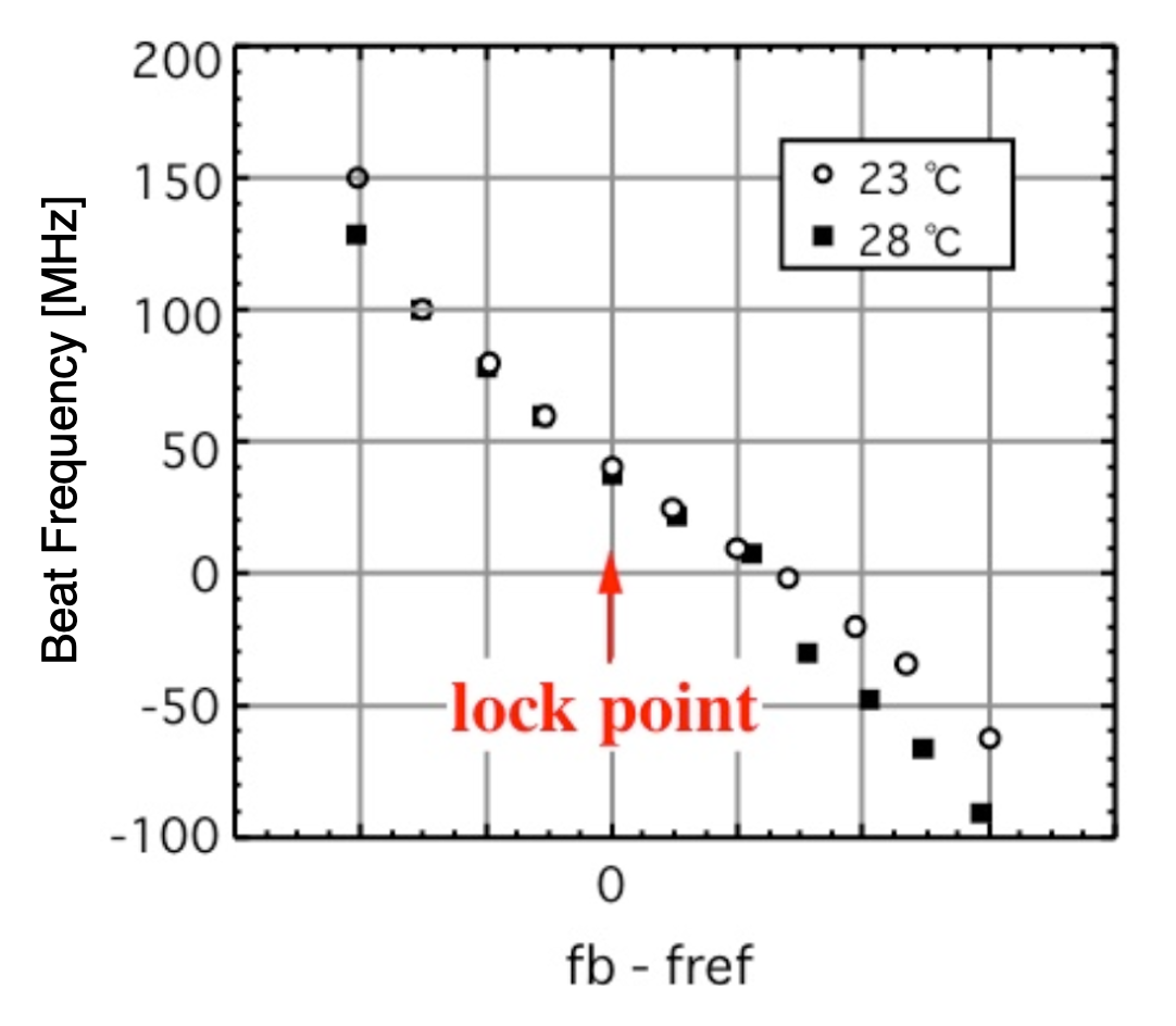
The Ne gain curve changes its shape with ambient temperature, affecting the relationship between mode position and control signal. In YS-307, referencing the iodine-stabilized laser used as a secondary length standard in the traceability system, we select a lock point with minimal sensitivity to ambient temperature, defined by (fb − fref = 0) (Fig. 3).
Two-stage stabilization robust to ambient temperature variation
YS-307 combines (1) conventional proportional control and (2) a proprietary zero-convergence, accumulated integral control. This two-stage scheme maintains (fb − fref = 0) regardless of ambient temperature changes (Fig. 4(a)). With proportional control alone, fb − fref varies with temperature (Fig. 4(b)). The two-stage design mitigates such influence.
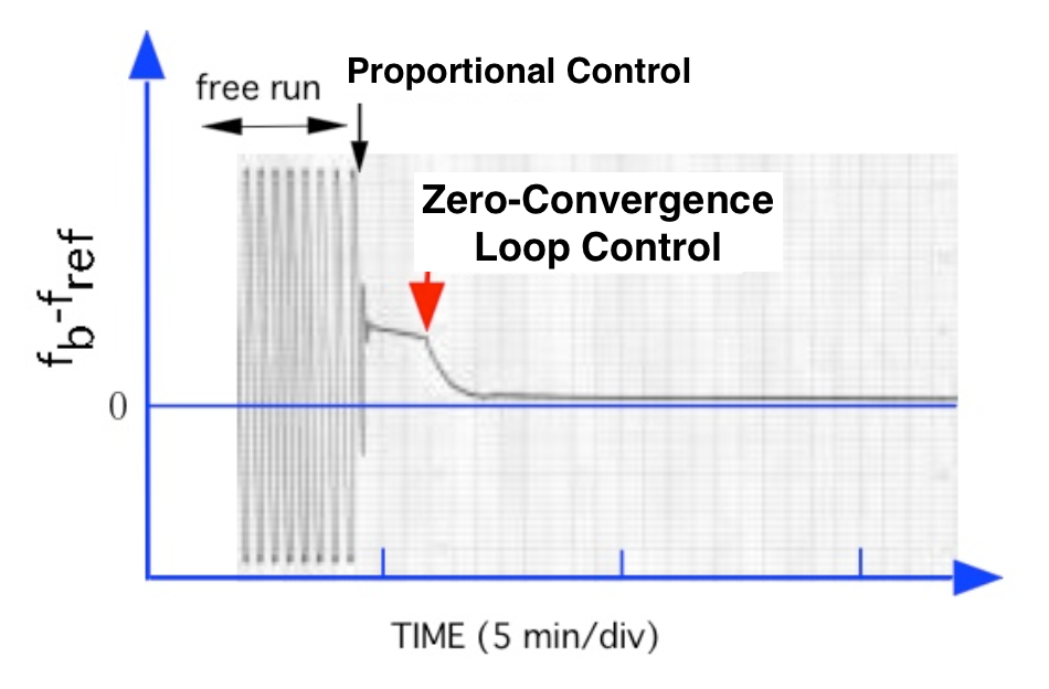
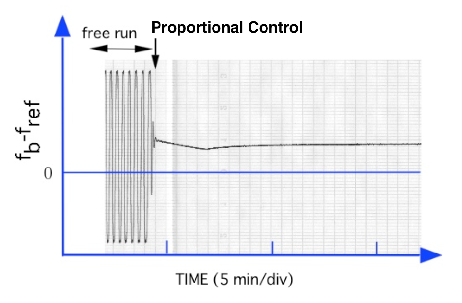
Fig. 4 Comparison of Stabilization Schemes
Dual-heater architecture to broaden the operating temperature range
The YS-307 series uses two heaters (main and sub) to control the cavity length. The main heater performs stabilization, while the sub heater compensates for ambient temperature drift. This dual-heater design expands the effective operating range of the two-stage control. Our measurements confirm proper operation over a range of ±20 °C centered around the starting temperature (25 °C).
10-11 Stability Across a Wide Range of Averaging Times
With these stabilization technologies, YS-307 achieves 10-11 stability over averaging times from 1 s to 1,000 s. Fig. 5 compares stability with a product using polarization-intensity stabilization (our QS series).

Related Links