1. Laser
Laser is named from “Light Amplification by Stimulated Emission of Radiation.” Laser is artificial light, and is generated by exciting a specific material with aritificial large energy from light, discharge, and so on.
1.1. Characteristics
Laser light is superior in some properties to spontaneous light. The main characteristics of laser is shown below.
① Monochromaticity: Spectrum width is very narrow,
② Directionality: Light is not dispersed and expanded,
③ Coherence: Light can interfere with each other,
④ Controllability: Output light can be easily modulated,
Since laser light is far stronger than and is superior in terms of monochromaticity and directionality to spontaneous light, laser beam can be focused by lens into a diffaction limit with a high energy density. This indicates that laser is superior in a focusing property and has a high brightness. Fig.1.1 schematically explains the laser characteristics shown above.
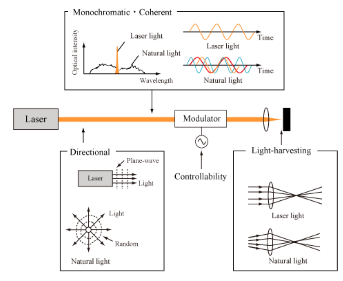
Fig.1.1 Features of Laser
1.2. Lasing operation and parameter
Laser is composed of an optical amplifier and an optical resonator. Laser output is obtained by light oscillations in an optical resonator. The lasing operation is either the continuous wave (CW) operation (for CW laser) or the pulsed operation (for pulsed laser). In CW laser, a constant power is continuously output. In pulsed laser, optical pulses are output with a constant repetition frequency. Fig.1.2 shows a schematic of the CW operation and pulsed operation.
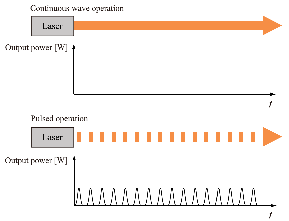
Fig.1.2 Continuous wave and pulse oscillation
A CW laser is characterized by an average power [W]. A pulsed laser is generally characterized by a pulse duration [s], a repetition rate [Hz], a pulse energy [J], and a peak power [W]. These parameters of pulsed laser are associated by the following expressions.
Average power [W] = pulse energy [J] × repetition rate [1/s]
Peak power [W] ~ pulse energy [J] / pulse duration [s]
Fig.1.3 schematically explains the relationship among these parameters of pulsed laser. Table 1.1 summarizes units of laser parameters which are frequently used.
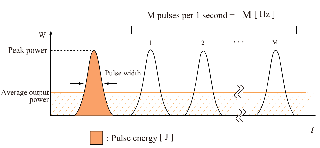
Fig.1.3 Relationship between various parameters of pulsed lasers
Table 1.1 Units for laser-related parameters
| Words | Units |
| Wavelength Spectral bandwidth |
m |
| Average output power Peak power |
W |
| PRR: Pulse repetition rate | Hz |
| Pulse width or pulse duration | s |
| Energy per pulse or pulse energy | J |
| loss Gain |
dB or dB/km |
| Beam quality M2 | – |
2. Principle mechanism
In this section, we describe fundamental items just enough for understanding a lasing mechanism in fiber laser without using mathematical expressions as little as possible.
2.1. Energy level
Before considering about an operation mechanism of laser, we describe an idea of energy level.
Atom consists of an atom core and a number of electrons. Electrons exist in discrete orbitals around an atom core. Usually, electrons dominate lower evergy orbitals to minimize the energy of atom. This state is called as ground state. The ground-state atom is stable.
When heat or light is given to the ground-state atom, electrons in the outer orbital, which has high energy, can be transferred to a further outer orbital. Then, the atom will gain energy. A diagram plotting the energy on the basis of the ground state for describing this higher energy state is called as enegry level diagram. The energy level of ground state is called as ground state. The process of transition of atomin energy level from the ground state to a higher-energy level is called pumping. The energy level of excited state is called as excitation level.
It is also possible to consider the energy level not only for atoms, but also for molecules and ions. As excitation methods, collision of atoms and molecules, and chemical reactions are used other than the optical pumping.(図1.4に関する記述なし)
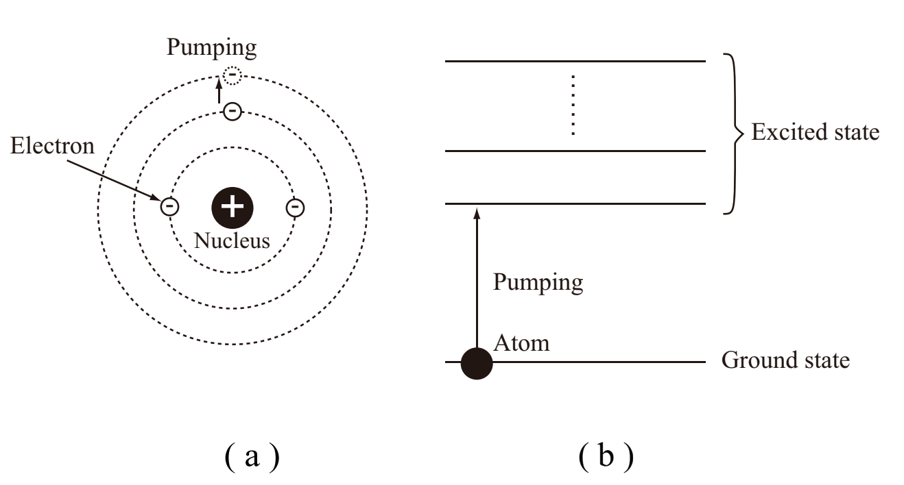
Fig.1.4 Atomic model and energy level diagram
2.2. Light absorption and emission
In order to understand the operation mechanism of laser, we have to understand light interactions with a material including absorption, spontaneous emission, and stimulated emission, and non-radiative transition (no direct relationshiop with light). Let us consider an energy level with an atom distribution density of N1 and a degeneration number of g1, E1 (ground level), and an energy level with an atom distribution density of N2 and a degeneration number of g2, E2. E2 is just required to be an upper level than E1 (not required to be neighbored to E1). This kind of model is called as two-level model. Fig.1.5 represents a light absorption and emission for a two-level model.
Provided that an atom at E1 state is irradiated by a photon with a frequency of ν that satisfies the Bohr condition, E2-E1=hν where h is the Planck constant, light absorption, spontaneous emission, stimulated emission, and non-radiative transition, which are directly associated with the operation mechanism of laser, are desribed as follows.
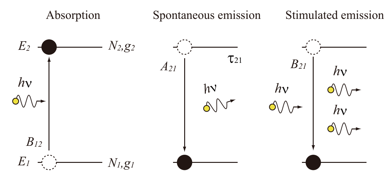
Fig.1.5 Light absorption and emission for a two-level model
2.2.1. Absorption
An atom at the energy level of E1 exhibits stimulated absorption and an absorption transition to E2 at a certain propability. A parameter representing what propability a photon is absorbed at is defined as B12, absorption transition rate. Bji is called as the Einstein B coefficient.
2.2.2. Spontaneous emission
An atom excited to the level E2 can spontaneously emit a photon with a frequency of ν and exhibits a transition to the low-energy and stable E1 level after a certain time (lifetime: τ21) is passed since the excitation. This process of the spontaneous light emission is called as spontaneous emission. The spontaneous emission can be a noise since it has a random polarization and phase, but it is a seed of laser light. A parameter representing a propability of photon emission is defined as an emission transition rate, A21. Aij is called as the Einstein A coefficient. The lifetime (τ) and the A coefficient for spontaneous emission are associated with a reciprocal relationship.
2.2.3. Stimulated emission
When an excited atom at the level E2 is irradiated by a photon with a frequency of ν, the excited atom is stimulated to emit a photon with the same phase at the same mode in the same direction as the incident direction of a photon. This phenomenon is a stimulated emission. The stimulated emission is the principle of light amplification, and primarily works for light amplification by stimulated emission of radiation, laser. A parameter representing a probability of stimulated emission is defined as a transition rate, B21, and is associated with the absorption transition rate, B12, and the degeneration number of level by g1B12=g2B21. A transition of stimulated emission attributed to the laser oscillation is called as laser transition. The upper energy level and lower energy level are called as laser upper-level and laser lower-level, respectively.
2.2.4 Non-radiative transition
The transition of energy from the laser upper level to the laser lower level can emit energy to a lattice vibration. This is called as non-radiative transition. It is determined by a sort of material which occurs with a high probability, the spontaneous emission or the non-radiative transition.
2.3 Gain and inverse distribution
In a system where atoms (or molecules) are excited to an excitation state, the absorption, spontaneous emission, stimulated emission, and non-radiative transition simultaneously occur. Let us consider that a medium is irradiated by light at a frequency of ν with an intensity of Iν=cρν/n where c is light velocity, n is refractive index of medium, and ρν is energy density at the frequency of ν. Provided an emission spectrum function, g(ν), an increase of light intensity per unit length of medium is expressed by the following equation,
Eq.1.2.1
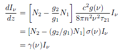
where σ(ν) is stimulated emission cross-section, and γ(ν) is gain. σ(ν) and γ(ν) are given as follows.
Eq.1.2.2
Eq.1.2.3
The stimulated emission cross-section (absorption cross-section) can be thought as a certain cross-section of atom, at which input photons exhibit stimulated emission (absorption). For a simple two-level model, the absorption cross-section and the stimulated emission cross-section are equivalent.
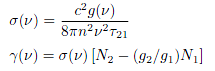
For N2>(g2/g1)N1 (In the case of non-degenerated two-level model, g1=g2, N2>N1), the stimulated emission is dominant over the absorption, then light is amplified (see Fig.1.6(a)). On the other hand, for the thermal equilibrium state (see Fig.1.6(b)), since a distribution density of atom is the Boltzmann distribution, we have N2<(g2/g1)N1 and a negative value of γ(ν). Therefore, the incident light is exponentially decreased as it travels longer in the medium. By the way, even if the intensity of incident light is larger, since the rates of absorption and stimulated emission for a single atom are the same, transitions to the level E1 increase, while transitions to the level E2 increase. In essence, we have N2<(g2/g1)/N1. A state of N2>(g2/g1)N1 is called as inverse population state. It is not possible to realize the inverse population (negative temperature) by optical excitations for the two-level model. In practical laser, the inverse population is realized by the following two methods.
Fig.1.6 Energy level diagram of (a) inverted distribution state and (b) thermal equilibrium state of two-level system
① Optical excitations with the third or fourth level
② Non-optical excitations with current injection, discharge, or chemical reactions
The method ① will be explained in the subsection 1.2.4. The method ② where semiconducting laser or gas laser is used will be explained in the section 1.4.
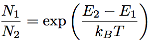
2.3.1. Boltzmann distribution
In a thermal equilibrium state at absolute temperature of T, an atom density, Ni (i=1,2,3,…), at energy level Ei, is typically represented by the Boltzmann distribution. Ni and Ei are associated by the following equation,
Eq.1.2.4
![]()
2.4 Three-level model and four-level model
In this section, we explain how the inverse population is realized for a medium of the three-level model and the four-level model with using the energy diagarm, and describe a rate equation for representing a temporal change in the inverse deistribution density and the photon density for the medium to be arranged in a resonator as a laser medium.
2.4.1. Three-level model
Fig.1.7 shows the energy level of the ideal three-level model. In this model, laser lower-level, E1, is the same as the ground state, the lower-level always has an atomic number distribution. Above the laser upper-state E2, the pumping level E3 with with a wideband width exists. For an efficiently producing an inverse population, the lifetime of the pumping level is required to be small, and a relaxation time of non-radiative traisition of the pumping level E3 to the laser upper-level E2, τ32, is required to be far smaller than the relaxation time of the pumping level E3 to the ground level E1. Under the requirements, the stimulated emission from the pumping level E3 to the ground level E1 barely occurs even with the intense pumping light irradiation, then the inverse population is realized. By the stimulated emission from the laser upper-level E2 to the ground level E1 in this condition, the laser oscillation is exhibited. The transition ratio of the population in the laser upper-level to the number of excited atoms in the pumping level is called as pumping qiuantum efficiency, ηp, and is defined by the following equation.
Eq.1.2.6
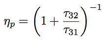
In an use of the pumping quantum efficiency, ηp, a transition rate of the ground level E1 to the laser upper-level E2 due to the pumping, W2, is associated with a transition rate of the ground level E1 to the pumping level E3 due to the excitation, W13, by Wp=ηpW13.
Provided the total atom density, Ntot=N1+N2, and dN2/dt=-dN1/dt since the relaxation of pumping level is fast, a rare equation for the inverse population density, N=N2-(g2/g1)N1, is expressed as follows,
Eq.1.2.7
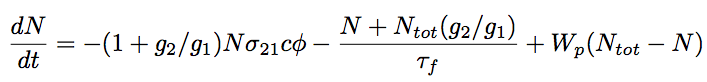
where φ is a photon density in a medium. τf is the fluorescence lifetime of the laser upper level (average time for an atom to be in the excited state), but is seen as equivalent to the spontaneous emission lifetime, τ21, on the purpose of simplification.
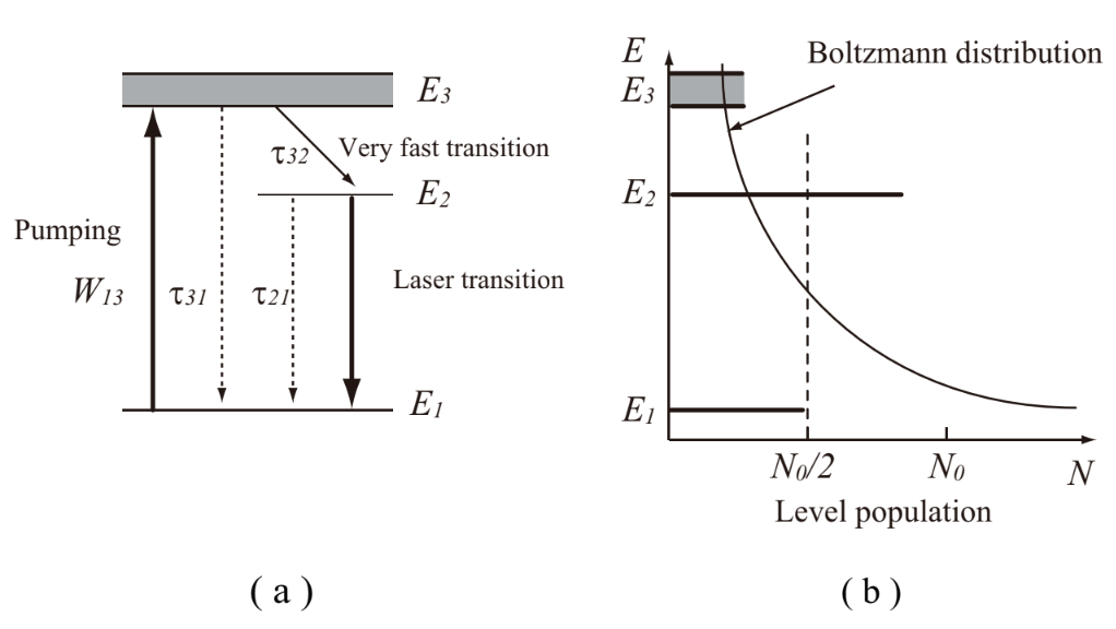
Fig.1.7 Schematic diagram of a three-level system
2.4.2. Four-level model
Fig.1.8 shows an energy diagram of the ideal four-level model. In this model, the laser lower-level is far larger than the ground level in terms of energy (E1>>kT), and the thermal pumping of the ground level to the laser lower-level never happens. Assuming that the lifetime of the pumping level E3 is far longer than the lifetime of the other levels, the density distribution of the pumping level E3 (N3) can be ingnored, then the total atom density is expressed as Ntot = N0 + N2 + N3. Additionally, since an ideal four-level laser allows an approximation of τ10~0, we obtain N1=0 and the inverse population density of N=N2.
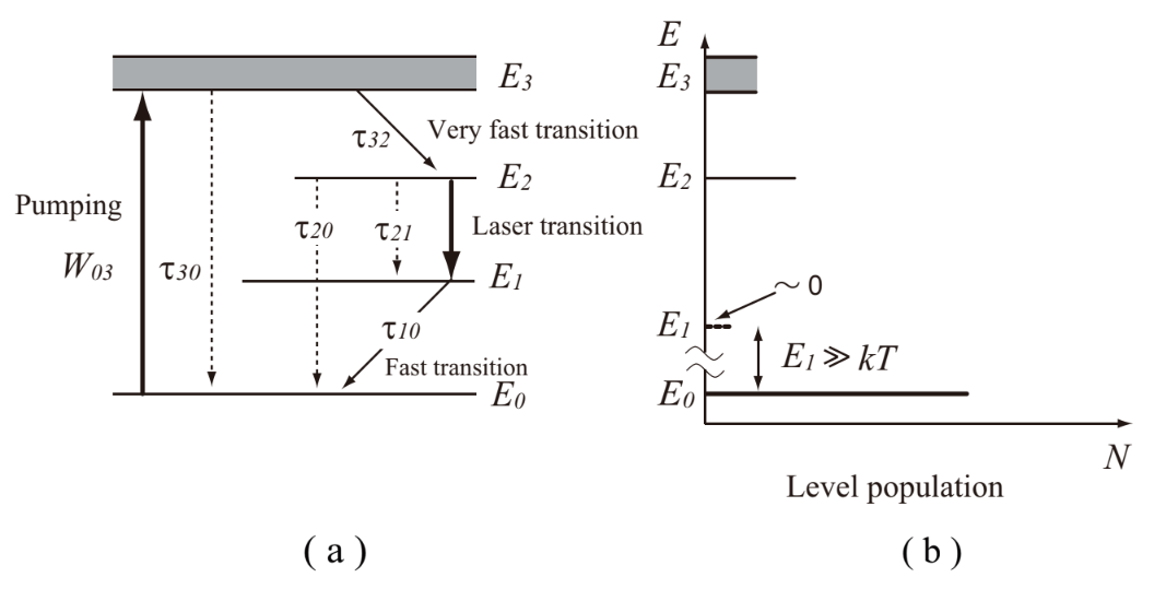
Fig.1.8 Schematic diagram of a four-level system
Then, the rate equation for the inverse population density is given as follows.
Eq.1.2.8
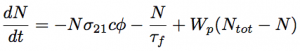
Fuorescence lifetime of the laser upper levelm τf, the pumping rate, Wp, and the pumping quantum efficiency, ηp, are expressed by the following equations, respectively.
Eq. 1.2.9
Eq. 1.2.10
Eq. 1.2.11
2.4.3. Comparison of inverse distribution
For the three-level model, a ground level is a laser lower level. Provided that E3 is ignorable, Ntot= N1 + N2 is obtained, then, the density distribution of laser upper level, N2, needs to be Ntot/2 or larger for realizing the inverse population. On the other hand, for the four-level model, the atom density distribution of laser upper level, N2, turns to be the inverse populatio density, N. Therefore, the three-level laser is not as efficient as the four-level laser, since the three-level laser requires relatively intense pumping power.
Assuming that the medium is in the steady-state and certain conditions of dN/dt=0 and φ=0 (photon density), we obtain the following equation derived from Eq.1.2.7.
Eq.1.2.12
![]()
For the four-level laser, the following equation is obtained from the Eq.1.2.8 in the same manner of deriving the Eq.1.2.12.
Eq.1.2.13
Here, we assume that the laser upper-level and the laser lower-levels are degenerated and the relationship of degeneration is given by g1=g2. Then, changes in the laser population density are represented in Fig.1.9 as functions of normalized pumping rate, Wpτf, which are given from Eqs.1.2.12 and 1.2.13. Fig.1.9 shows that the efficiency of three-level laser is low.
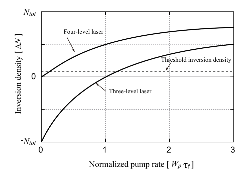
Fig.1.9 Excitation rate characteristics of inversion distribution changes in three-level and four-level systems
2.4.4. Spectral line width
A spectrum of spontaneous emission light and absorbed light is not a single line which satisfies E1-E2=hν, but a spectral shape centering at the spectral line with a certain width. The broadening of spectral shape is a laser gain curve, ad determines lasing properties. A narrow spectrum is appropriate for single frequency operation, while a broad spectrum is appropriate for wavelength tunable operation. The spectral broadening is categorized into two types, homogeneous broadening and inhomogeneous broadening. Laser medium has a property of mixture of homogeneity and inhomogeneity.
2.4.4.1. Homogeneous broadening
The homogeneous broadening is inherent to each atom in a medium. The homogeneous broadeninng can be spontaneous broadening, Stark broadening, collision broadening, and so on.
The spontaneous broadening is a primary broadening yielded from lifetime of a pumping level and the frequency uncertainty. A width of spontaneous broadening between two pumping levels with lifetimes of τi and τj (spontaneous width), Δνij, is expressed by the following equation.
Eq.1.2.14
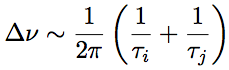
Assuming that the lower level is the ground state, lifetime of the ground state is infinite. Then, as the lifetime τf is short, the spontaneous width is large. The shape of spontaneous width is the Lorentzian shape as is shown in Fig.1.10.
The Stark broadening is due to degeneration of energy level caused by external electric field. Stark level yielded by the degeneration makes the lifetime very short, and the spectral width very large.
The collision broadening is yielded in gas laser since a lifetime of pumping level becomes shorter when atoms (or molecules) collide with each other and the pumped atoms lose their energy. The collision broadening is dominant for such a gas laser as excimer laser operating with high gas pressure discharge.
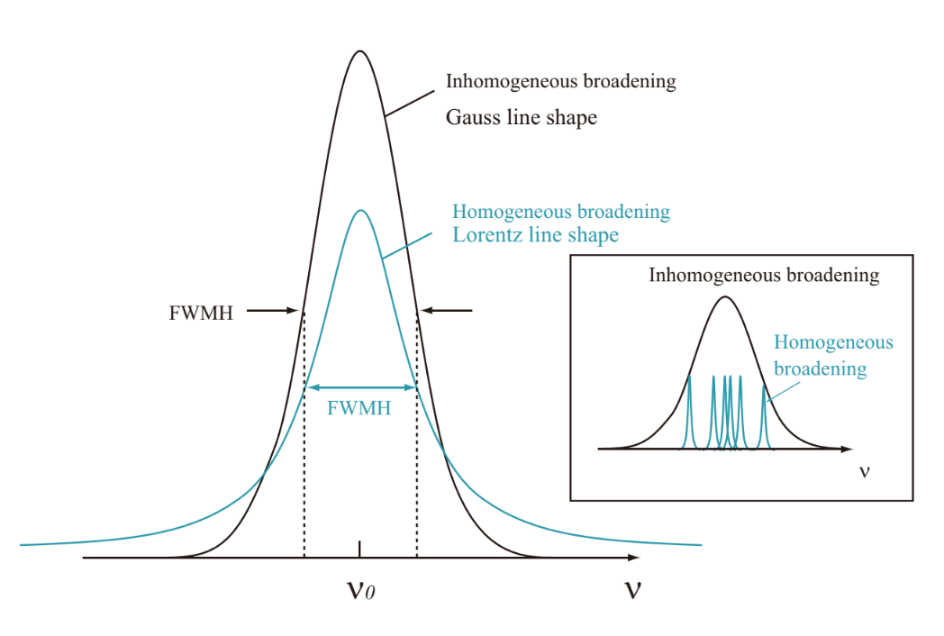
Fig.1.10 Lorentzian and Gaussian spectra
2.4.4.2. Inhomogeneous broadening
The inhomogeneous broadening is a phenomenon that various frequencies are generated by a variety of influences and the spectrum is broaden. The inhomogeneous broadening can be a strain caused by lattice defect or inhomogeneity of magnetic or electric field (crystalline field) for solid-state laser, and Doppler broadening for gas laser.
In a crystal of solid-state laser, the crystalline field is not uniform since the crystal is imperfect. As a result, a large inhomogeneous broadening is yielded. In glass doped with rare earth ion, because host ions are randomly distributed, the inhomogeneous width is relatively largely broaden compared with the crystalline solid-state laser.
The Doppler broadening is yielded by emission of light with different frequencies by the Doppler effect of each atom (or molecule) with irregular thermal motion. The Doppler broadening is dominant in gas laser operating with low pressure discharge. Since the velocity distribution of gas molecules obeys Maxwell distribution, the shape of Dopper broadening is Gaussian (normal distribution) function shape. Fig.1.10 shows a Gaussian function and represents that the Doppler broadening is a superposition of spontaneous broadening.
3. Lasing property
Let us consider a Fabri-Pelot resonator arranging an inverse population medium of lenght of l and equibrillium flat mirrors at the both edges of the medium as shown in Fig.1.11.
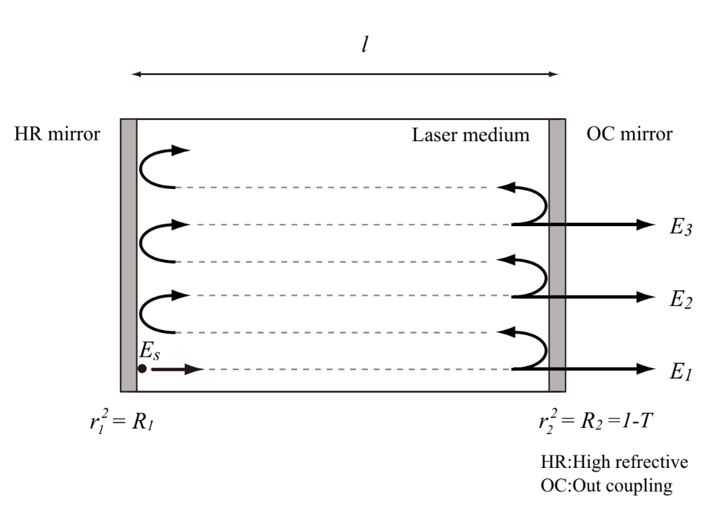
Fig.1.11 Fabri-Pelot resonator
Electric field of light propagating in the resonator is expressed as classical electromagnetic field as follows.
Eq.1.3.1
![]()
Eq.1.3.2
![]()
E0 is amplitude of electric field, ω is angular frequency, and k’ is wavenumber of medium. In Eq.1.3.2, k is a propagation constant and is given by k=2π/λ, Δk is wavenumber shift by dispersion, γ(ν) is gain coefficient, and α is absorption coefficient.
First, we assume that an electric field Es is generated by spontaneous emission at the total reflection mirror position of z=0. The electric field, Es, partially penetrates over the out mirror and is extracted to the outside the resonator. However, since the reflectivities of both mirrors are high, most of the light travels forward and backward in the resonator, and is amplified by the stimulated emission from the inverse population medium. Light emitting from the output mirror, Eout, is expressed by the following equation,
Eq.1.3.3
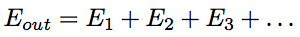
where each field component is give by the following equations.
Eq.1.3.4
Eq.1.3.5

Therefore, Eq.1.3.3 can be rewritten as follows,
Eq.1.3.6
where r1 is reflectivity of the total reflection mirror for the electric field, and r2 and t2 are reflectivity and transmittance of the output mirror, respectively. Because lasing state corresponds to a condition that the denominator of Eq.1.3.6 is 0, the real and imaginary parts of output electric field are represented by the following equations, respectively.
Eq.1.3.7

Eq.1.3.8
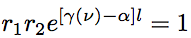
Eq.1.3.7 is the resonance condition, and represents a state that a phase of electric field propagating forward and backward in the resonator does not change at a certain position. Eq.1.3.8 is the oscillation condition, and represents a state that an amplitude of electric field propagating forward and backward in the resonator does not change at a certain position.
3.1. Resonance condition
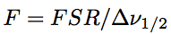
For light to stably exist in the Fabri-Pelot resonator, a standing wave needs to exist in the resonator (where a phase delay after a round-trip light propagation in the resonator is 2πm) and a node of the standing wave must be located at the mirror as shown in Fig.1.12(a) and (b). Then, the resonator length, l, is the integral multiple of a half of the wavelength, λ.
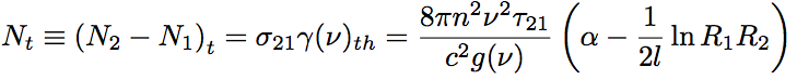
This is the resonance condition represented by Eq.1.3.7. Light with a frequency satisfying Eq.1.3.7 is called as longitudinal mode, and represents an electric field distribution of the standing wave existing along the axial direction of the resonator. On the other hand, transverse mode represents a distribution of the standing wave on the beam cross-section. “Mode of optical fiber” described in latter parts of this book indicates mostly the transverse mode. Fig.1.12(c) schematically explains the longitudinal mode by setting frequency and transmittance to the horizontal and vertical axis, respectively.
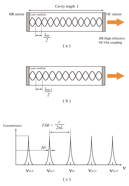
Fig.1.12 Schematic of longitudinal mode of laser
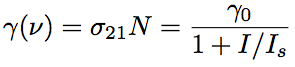
In the resonance condition, the transmittance takes a local maximum for the resonance frequency, which is the center frequency of longitudinal mode, then, the longitudinal modes (local maximums of transmittance) appear with a constant interval. This interval is called as transverse mode interval or free spectral range (FSR). Transmission characteristics of a resonator (resonance sharpness) is exhibited by Finesse. Provided FWHM of a longitudinal mode, Δν1/2, Finesse is given by the following equation.
Eq.1.3.9
In case a laser medium does not exist in the resonator (the case of passive resonator), since Δk=0 (and k=2π/λ) in Eq.1.3.7, the resonance frequency, νm, is given as follows.
Eq.1.3.10
![]()
In case a laser medium exists in the resonator, by considering a phase shift due to stimulated emisstion, the oscillation frequency, ν, is expressed by the following equation,
Eq.1.3.11
![]()
where ν0 is the gain center frequency, and Δν is the gain width at half maximum of medium. Eq.1.3.11 indicates that ν is shifted to νm when the resonance frequency, νm, is not equivalent to the center frequency of gain, ν0. This frequency shift is known as the frequency pulling effect.
The longitudinal modes infinitely exist with a frequency interval of c/2πl, but in practice, the laser oscillation is possible only for a frequency in the spectral range for a laser medium to exhibit the amplification operation (in the range of gain curve). In order to exactly obtain light with a specific wavelength from an optical resonator, the resonator length, l, must be restrictly maintained, and temperature change in the environment and mechanical fluctuation need to be cared.
3.2. Oscillation condition
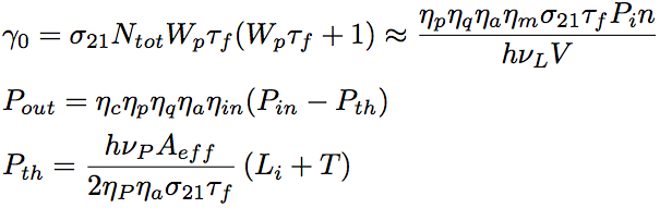
An atom excited to the laser upper level by the pumping light yields light via the spontaneous emission (or the stimulated emission). When a part of the yielded light is in the resonant mode of an optical resonator, the light is amplified by the stimulated emission by every round trip inside the resonator. But, in a weak pumping state, since the loss of resonator exceeds the gain of amplification, light is decayed after each round trip in the resonator. Here, the loss of resonator is the sum of the coupling loss (T), which is caused by the light exit out of the resonator through the transmission over the output mirror, and the residual loss (Li), which is based on the absorption, scattering and diffraction loss in the resonator. As the pumping light becomes intense, the gain of stimulated emission increases, since the number of atom excited to the laser upper level increases. As a result, with some pumping light intensity, the gain of amplification and the loss of resonator for a round-trip becomes equivalent to each other. Subsequently, because the gain and loss are balanced, the amplitude of light intensity does not change regardless of the number of round-trips in the resonator. This state is called as the oscillation in laser, and Eq.1.3.8 is the oscillation condition.
Eq.1.3.8 gives the gain coefficient at the oscillation threshold, γth, as shown below,
Eq.1.3.12
![]()
where R1 and R2 are reflectivities for the light intensity and given by R1=r1^2 and R2=r^2. The inverse population densitym, Nt, is expressed by the following equation.
Eq.1.3.13
3.2.1. Excitation intensity and gain change
Small-signal gain coefficient (unsaturated gain coefficient), γ0, is a gain coefficient for the photon density of φ=0. A gain for light to penetrate through a laser medium, G0=γ0l, is called as small-signal gain. Provided the intensity of signal light traveling through the laser medium, I, the gain coefficient, γ(ν), is expressed by the following equation,
Eq.1.3.14
where Is is the saturated light intensity and is defined as light intensity for the gain coefficient, γ(ν) to be a half of the smal-signal gain coefficient, γ0. Eq.1.3.14 indicates that the gain coefficient, γ(ν), decreases as the light intensity in the resonator, I, increases. As the light intensity increases, the stimulated emission increases, then the number of atoms in the laser upper level decreases (the density difference from the laser lower level decreases) and the inverse distribution density decreases. This phenomenon is called as gain saturation, and determines the output intensity of laser and the maximum output of optical amplifier. Fig.1.13 represents the gain characteristics of Eq.1.3.14.
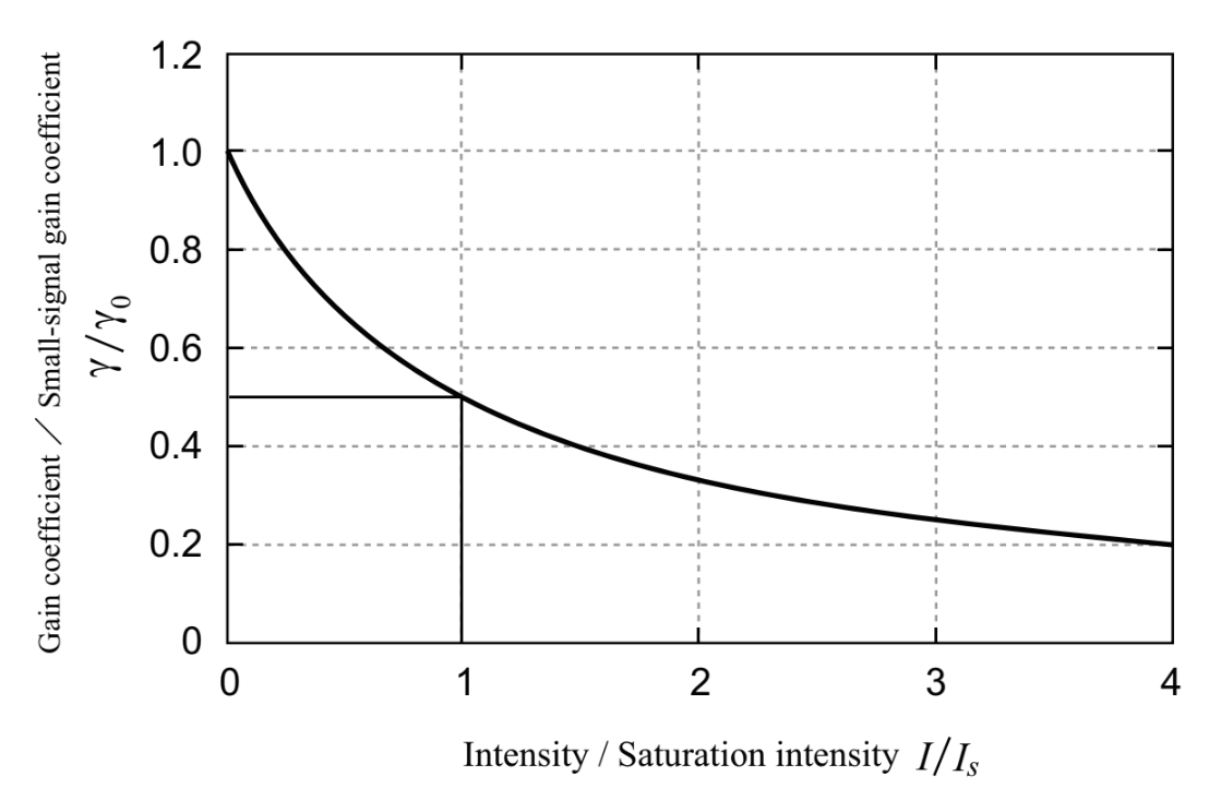
Fig.1.13 Signal Light Intensity Characteristics of Gain
Provided the intensity of light (signal light for causing the stimulated emission) in the Fabri-Pelot resonator, Ic, the gain coefficient is expressed by the following equation.
Eq.1.3.15
![]()
Because the forward and backward waves are considered, Ic has a coefficient of 2. Provided the light intensity of Ic = cφhν, the saturated light intensity of three-level and four-level laser can be derived from Eq.1.3.15 and the inverse population calculated from Eqs.1.2.7 and 1.2.8 for the steady state. For the three-level laser, the saturated light intensity is given as follows.
Eq.1.3.16
For the four-level laser, the saturated light intensity is represented as follows.
Eq.1.3.17
For the four-level laser, the saturation gain intensity is approximated by using Wp >> 1/τf.
3.2.2. Oscillation threshold and slope efficiency
Here, we consider the case when a laser medium is radiated by the pumping light with a power f Pin, and discuss the pumping power property of laser light. As parameters of a laser medium, we consider the following 7 items.
① Mode volume of a laser medium, V
② Pumping quantum efficiency, ηp:
Rate of transition to the laser upper level to the number of atoms pumped to the excited levels
③ Atom quantum efficiency ηq=νL/νP:
Proportion between the laser photon energy, hνL, and the pumping photon energy, hνP
④ Pumping light absorption efficiency ηa:
Absorption fraction of pumping light by a laser medium
⑤ Mode matching efficiency ηm:
Overlapping fraction between lasing and pumping areas
⑥ Coupling efficiency ηc=T/(Li+T):
Fraction represented by using the transmittance, T, and residual loss, Li, of output (coupling) mirror
⑦ Effective cross-section of laser light Aeff
With considering these items, we derive the small-signal gain coefficient, γ0, the lasing output, Pout, and the lasing threshold, Pth, below. Fig.1.14 represents the pumping power property of laser output.
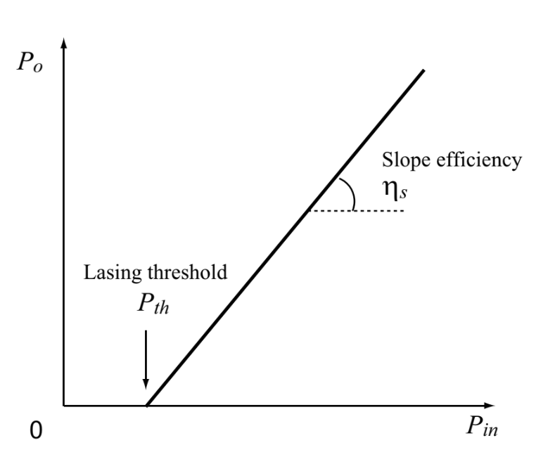
Fig.1.14 Excitation power characteristics of laser output
3.2.2.1. For three-level laser
Assuming that the number of degeneration of the laser upper level and lower lever are the same (g1=g2), the small-signal gain coefficient, γ0, and the output power, Pout, for the three-level laser are expressed by the following equations.
Eq.1.3.18
Eq.1.3.19
Eq.1.3.20
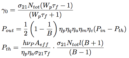
Eq.1.3.21
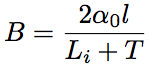
3.2.2.2. For four-level laser
The small-signal gain coefficient and the output power for the four-level laser are expressed by the following equations.
Eq.1.3.22
Eq.1.3.23
Eq.1.3.24
Thus, in case the puming power exceeds the laser oscillation threshold, the laser output power, Pout, increase in proportion to the pumping power, Pin (gain is constant regardless of the pumping light intensity). This fraction of increase is called as slope efficiency, ηS. Since the slope efficiency for the three-level laser is accompanied by the factor or 1/2(1-1/B), the slope efficiency for the three-level laser is limited to be smaller than the half of the slope efficiency for the four-level laser, as is understood from Eqs.1.3.19 and 1.3.23. Additionally, provided that the transmittance, T, increases, the increasing rate of slope efficiency for the four-level laser is larger than that for the three-level laser.
Here we compare the laser oscillation thresholds between Eqs.1.3.20 and 1.3.24. As the loss, Li+T, becomes close to 0, the oscillation threshold for the four-level laser also becomes close to 0, while the oscillation threshold for the three-level laser becomes a finite value. Therefore, a laser medium for the four-level laser has a lower oscillation threshold and a higher slope efficiency compared with the three-level laser. This can be confirmed by the pumping rate property of inverse distribution change shown in Fig.1.9.
3.3 Lasing spectrum
With considering the resonance condition and the oscillation condition explained in subsection 1.3.1 and 1.3.2, respectively, the spectrum of light extracted from the laser resonator will be described separately for laser media with the homogeneous and inhomogeneous broadenings (refer to subsection 1.2.4).
3.3.1. For laser medium with the homogeneous broadening
Fig.1.15(a) represents the gain curve (gain spectrum), the loss of resonator, and the resonance frequency (ν-3, ν-2, ν-1, ν0,…) of passive resonator for a laser medium with the homogeneous broadening. For the pumping intensity to be smaller than the laser oscillation threshold, the inverse population density is proportional to the pumping light intensity, and the gain, γ, is proportional to the emission light spectrum function, g(ν) (see Fig.1.15(a)). As the pumping light intensity increases, the gain at the center resonance frequency ν0, G=γl, is equivalent to the loss of resonator, and the laser oscillation occurs at the frequency of ν0 (see Fig.1.15(b)). In this condition, even if the pumping light power increases, the inverse population density does not increases, and the gain curve is fixed by the loss of resonator (gain threshold) at ν0, then is constant. Therefore, since the gain at resonance frequencies excluding ν0 is smaller than the loss of resonator, the oscillation does not occur. However, the oscillation light intensity increases in proportion to the pumping intensity (see Fig.1.15(c)). In summary, laser with an ideal homogeneous broadening can exhibit the oscillation only for a single longitudinal mode. This sort of laser oscillation is called as single mode oscillation.
3.3.2. For laser medium with the heterogeneous broadening
Fig.1.15(d) represents the gain curve (gain spectrum), the loss of resonator, and the resonance frequency (ν-3, ν-2, ν-1, ν0,…) of passive resonator for a laser medium with the inhomogeneous broadening. Also in a laser medium for the inhomogeneous broadening, for the pumping intensity to be smaller than the laser oscillation threshold, the inverse population density and the gain γ are proportional to the pumping light intensity (see Fig.1.15(d)). AS the pumping intensity increases, the gain at the center resonance frequency ν0, G=γ0l, is equivalent to the loss of resonator, and the laser oscillation begins to occur at the frequency of ν0 (see Fig.1.15(e)). These behaviours are the same as the behaviours for the homogeneous broadening medium, but behaviuors change for more intense pumping intensity.
The gain at ν0 is fixed by the loss of resonator, but the gain at other frequencies increases as the pumping intensity increases. When the gain at a certain resonance frequency becomes equivalent to the loss of resonator, the oscillation at the resonance frequency starts. Subsequently, since the gain at each resonance frequency is fixed, the gain curve has dips at each resonance frequency (see Fig.1.15(f)). This phenomenon is called as spectrum hole burning (or simply called as hole burning). The gain curve after the hole burning is called as saturation gain curve.
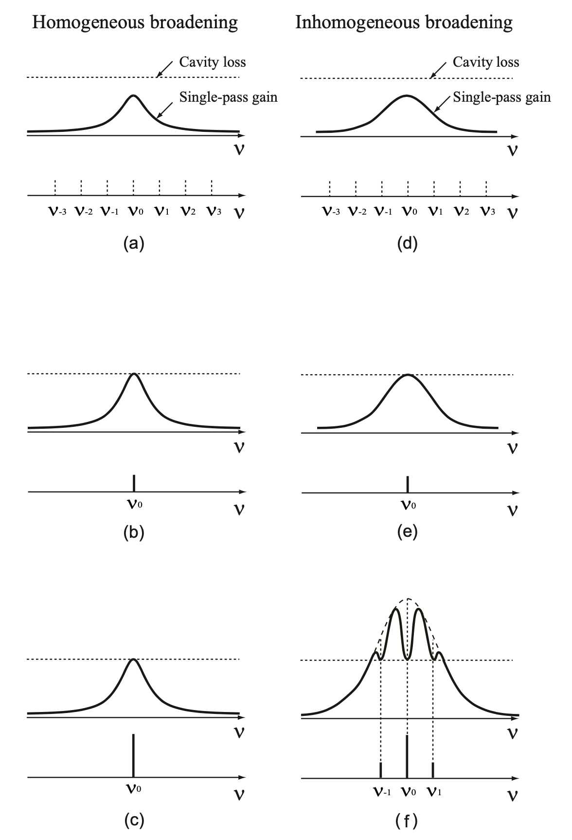
Fig.1.15 Uniform and non-uniform spread gain curves, longitudinal and oscillation modes
Spatial hole burning The spectral hole burning can be simply explained as that a hole is generated in the inverse population density in the frequency domain, while spatial hole burning is explained as that a hole is generated in the inverse population distribution in the space of gain medium.
In the Fabri-Pelot resonator, the spatial hole burning is yielded since the a standing wave is formed. While the inverse population density at an anti-node of the standing wave decreases by the stimulated emission, the inverse population density at a node is almost kept since simulated emission hardly occurs. In these cases, a neighbored longitudinal mode consumes the residual gain in space and oscillates. Thus, the spatial hole burning can be a cause of multiple oscillation of longitudinal mode. Therefore, in order to avoid the spatial hole burning, a ring resonator where the oscillation is yielded by using mirror and isolator with circular light propagatation in the unidirection is sometimes employed.
3.4 Pulsed laser
In this subsection, the pulsed laser operation shown in Fig.1.2 is briefly described. The pulsed laser operation is based on the CW laser operation and can be realized by either of the following 3 methods. The direct modulation method, the Q-switching method, and the mode-locking method are briefly described below.
3.4.1. Direct modulation method
A method for obtaining a pulse shape is either a method where the beam output of CW laser is on and off by using a mechanical shutter or a method where a pumping source of resonator is pulse-controlled. For the high-power resonator, the latter method is dominantly employed. The direct modulation method can control a pulse shape and arbitratily modulates a pulse duration in the range of ps~ms. The direct modulation method is applicable for hole-drilling processing and optical communication, in which the thermal influence is better to be minimized.
3.4.2. Q-switching method
In Q-switching pulsed operation, after the inverse population in a laser medium becomes sufficient, the laser oscillation is rapidly induced, then optical laser pulses with huge energy are output with a certain interval. The pulse duration is in the approximate range of µs~ns. The Q-switching method is applicable to the micro-processing, the hole-drilling processing, the groove processing, and the marking on such precision components as electronic components and semiconductor parts.
3.4.3. Mode-locking method
By setting the period of given modulation to the round time of light propagating in the laser resonator (synchronizing and oscillating longitudinal modes in the resonator), the mode-locking occurs. The pulse duration is in the range of fs~ps, which is the shortest pulse obtained among the three pulsed laser operation methods. Generally, the pulse energy obtained by the mode-locked method is relatively small compared with that of the Q-switching method. The repetition frequency is determined by the resonator length. As the resonator length becomes shorter, the repetition frequency becomes higher. The mode-locked method is applicable to the nonthermal processing, the nonlinear optics, and the seed light for terahertz light and supercontinuum light.
4. Sorts of laser
The history of laser started at 1960 from the ruby laser oscillation, which is a three-level solid-state laser. Subsequently, new types of laser materials or media such as gas laser, semiconducting laser, dye laser, and fiber laser was eagerly studied. CO2 laser, excimer laser, Nd:YAG laser, and fiber laser are currently often used for industries.
In this section, we categorize lasers by a type of gain medium, and describe gain medium, pumping method, oscillation configuration, and oscillation wavelength of a typical laser for each type of gain medium. Table 1.2 shows items for featuring laser, and each type of laser. The details are discussed in the text below.
Table.1.2 Items for featuring laser, and each type of laser
| Gain medium | Excitation method | Oscillation wavelength | Oscillation operation | |
| Liquid | Pigment | Light | Ultraviolet~Infrared | CW, pulse |
| Gas | HeNe | Electrical discharge | Visible~Infrared | CW |
| Noble gas ion HeCd |
Ultraviolet~Visible | CW | ||
| Excimer | Ultraviolet | pulse | ||
| Carbon dioxide gas | Far infrared | CW, pulse | ||
| Chemistry | Chemical reaction | Infrared | CW | |
| Semiconductor | Compound semiconductor | Electric current | Ultraviolet~Infrared | CW, pulse |
| Solid | Nd: YAG Yb: YAG |
Light | Infrared | CW, pulse |
| Titanium Sapphire | Ultraviolet~Infrared | |||
| Optical fiber | Er, Yb, Tm | Light | Infrared | CW, pulse |
4.1 Liquid laser
Liquid laser employs liquid as a laser medium. An organic dye where dye molecules are disolved in organic solvent (alchol: ethylene glycol, ethyl, methyl) is mostly used as a medium of the liquid laser. Among practically used liquid lasers, the dye laser employing the organic dye as a laser medium is mostly used.
4.1.1. Dye laser
There are a number of sorts of dyes existing and it is possible to synthesize new types of dye. Therefore, it is thought that the laser oscillation can be realzied with using more than several hundreds types of organic dyes. A typical medium for dye laser is rhodamine 6G (R6G). R6G is used for applications to laser spectroscopies and cures for a reddish face.
Since a dye molecule has very wide emission spectrum (ca. 320-1200mm), the dye laser is used as wavelength-tunable laser. The dye laser can be operated in both CW and pulsed oscillation. Because the emission spectrum is broad, the dye laser is used also as mode-locked ultrashort pulsed laser. However, since the dye laser has some weak points such as the short lifetime and the limited output, the dye laser is recently replaced by a wavelength tunable solid-state laser such as titanium sapphire laser. Additionally, because of the request for a transition to RoHS regulation conforming product in the world, the production and distribution of dye laser are partially stopped.
4.2. Gas laser
Gas laser utilizes gas molecule as a laser medium. Mostly, the pumping is done by discharge to glass tube (or ceramic tube) including the gas. Electrons accelerated by the discharge give energy to atoms (or ions, molecules) in the gas laser medium, and excite the atoms to the pumping level. As a result, the inverse population is formed. Fig.1.16 shows a schamatic picture of a basic gas laser. The longitudinal discharge system represented in Fig.1.16(a) is utilizable at a low gas pressure for stable discharge, which is required for the continuous oscillation (discharge is stable for the low gas pressure). On the other hand, the transverse discharge system represented in Fig.1.16(b) is appropriate for high power pulsed operation, because the transverse discharge method it can rapidly give a huge amount of energy to a gas medium and is utilizable at a high gas pressure (HIgh power gas laser can be realized by increasing the density of laser medium). The resonator shown in Fig.1.16 has a configuration that the total reflection mirror and the output mirror are attached at the left and right edges of glass tube, respectively, while there is another resonator configuration where a Brewster window is attached to the glass tube and a mirror is arranged at the outside of the glass tube (external mirror system). By using the external mirror system, linearly polarized laser beam is obtained for the gas laser, too.
Gas types for laser media are atomic gas (for HeNe laser, noble gas laser, and metal vapor laser), excimer, and molecular gas (for N2 laser and CO2 laser). In the following text, we briefly describe these gas lasers.
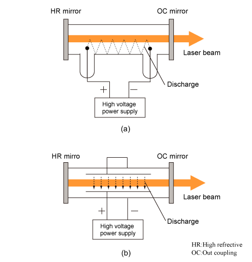
Fig.1.16 Schematic of gas laser
4.2.1. HeNe laser
A medium of helium-neon (HeNe) laser is a gas mixture of 75% or higher percentage of He and 15% or lower percentage of Ne. HeNe laser is identified as an atomic gas laser. In HeNe laser, He receives energy from electrons via discharge, then gives the energy to Ne via collisions and excites Ne to the pumping level. Thus, Gas laser frequently employs gas which is not directly related to the luminescence. Fig.1.17 represents the primary energy level structure of He and Ne in HeNe laser.
When HeLe laser was first developed in 1960 by Javan, Bennet, and Herriott from the Bell laboratory, its oscillation wavelength was 1152nm. After the realization of the red osciilation at 632.8 nm in 1962 by White and Rigden, the wavelength of 632.8nm is general for HeNe laser. HeNe laser ha other oscillation lines in green (543.5nm), yellow (594.1nm), orange (612.0nm), and near infrared (1523nm and 3391nm). The output power is as low as around 50mW. However, because the laser beam profile is very close to the gaussiain distritbution and the oscillation wavelength is very stable for a long period, HeNe laser is used for interferometric measurement and laser microscope.
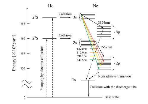
Fig.1.17 Main energy level structure of He and Ne atoms in HeNE laser
4.2.2. Noble gas laser
The medium of noble gas laser is mostly Argon ion (Ar+) or Krypton ion (Kr+), which is ionized by discharge. Noble gas laser is also called as noble gas ionic laser. Principle oscillation lines of Ar ion laser are in blue (488.0nm) and green (514.5nm). Principle oscillation lines of Kr ion laser are in the range of 450~670nm. Table 1.3 summarizes the media and the oscillation wavelengths for noble gas laser. Because the output power is relatively high (ca. 25W for Ar ion laser), noble gas laser is widely employed for entertainment purposes such as laser show and laser display, processing, and researches. However, the high power laser needs high current since the ionization of noble gas is necessary for the oscillation.
Table 1.3 the media and the oscillation wavelengths for noble gas laser
Numbers in parentheses () indicate the number of oscillation lines.
| Ion | Bandwidth | Wavelength |
| Ar+ | Ultraviolet Visible Infrared |
275.4-390.8 nm (16) 408.9-528.7 nm (13) 1090 nm |
| Kr+ | Ultraviolet Visible Infrared |
337.5-356.4 nm (3) 406.7-676.4 nm (13) 752.5-858.8 nm (5) |
4.2.3. HeCd laser
Helium-cadmium (HeCd) laser is operated by discharge in He gas with voparized (atomized) Cd, which is obtained by heating over 250 degrees Celsius. He atom plays a similar role in HeCd laser to HeNe laser. HeCd laser is identified as metal vapor laser in atomic gas laser. The oscillation lines are 325nm and 442nm in the CW operation. These two oscillation lines can be simultaneously output. The output power of these two lines are around 150mW for 442nm and around 40mW for 325nm. HeCd laser is mainly used for biotechnology researches and optical three-dimensional fabrication.
Copper vapor laser is also a metal vapor laser as well as HeCd laser. The copper vapor laser is operated by discharge in noble gas such as He, Ne, and Ar with voparized copper via heating over 1500 degrees Celsius. The copper laser operates with pulsed oscillation at 511nm and 578nm lines. At a repetition rate of several tenth kHz, the average output power of several tenth W is obtained. However, because the operation cost is very expensive, the copper laser is replaced by solid-state laser and semiconducting laser, and is rarely used.
4.2.4. Excimer laser
Excimer laser utilizes excimer as an oscillation medium. The excimer (abbreviated from excited dimer) is a coupling molecule out of an atom or a polyatom in the electronic excited state and an atom or a polyatom in the electronic ground state. The excimer laser operates at the pulsed oscilation in the UV range. The excimer is given by discharge excitation of a gas mixture of noble gas (Ar, Kr, and Xe) and halogen (F, Cl, Br, and I) at a high pressure. The oscillation wavelength is tuned by changing the fraction of noble gas and halogen in the gas mixture. Table 1.4 summarizes media and corresponding oscillation lines of excimer lasers currently available in the market. In typical excimer lasers, the pulse duration is around 30nm, and the repetition rate is around 300Hz.
The output power of excimer laser is the highest among UV lasers for processing. An average output power of 540W and a pulse energy of 1J at 600Hz repetition rate are achieved. However, the beam quality is not good and the beam is typically multimode, because laser light is output from the resonator after only a few round trips in the resonator since the excimer laser has a high gain. On the other hand, the speckle is ignorable since the coherence is low. Therefore, the excimer laser is typically used for uniformly illuminating a large region by using homogenized optics with fly eye lens. In the industry, the excimer laser is used as a light source of a laser annealing apparatus for manufacturing flat panel display and a semiconductor exposure apparatus. The other uses are for research and development, and medical applications such as lasik surgery and ELCA.
Table 1.4 media and corresponding oscillation lines of excimer lasers currently available in the market
| Excimer | Wavelength |
| F2 | 157 |
| ArF | 193 |
| KrCl | 222 |
| KrF | 248 |
| XeCl | 308 |
| XeF | 351 |
4.2.5. Carbon dioxide laser
The medium of carbon dioxide (CO2) laser is a gas mixture of helium, nitrogen, and carbon dioxide. Nitrogen in the gas mixture plays the following three roles; Nitrogen gives energy to CO2 and excites CO2 to the pumping level; Nitrogen receives energy from CO2 and relaxes CO2 from the laser lower level to a far lower level; Ntrogen removes heat generated via discharge. CO2 laser is the most common in the industry, and is used for cutting, drilling, weld, and surface modification of metal and non-metal. CO2 laser with several kW to 20kW output is used for processing. RF pumping system with sealed-off operation is widely adopted for 200W output or less. In CO2 laser, the oscillation occurs between vibrational states of carbon dioxide molecules. The oscillation lines are in the far infrared region (9.2~10.8µm), especially at 10.6µm ad 9.6µm. Materials transmissive in the visible range, such as water and glass, exhibit a very large absorption coefficient in the wavelength range of 10µm. CO2 laser is used for rhe Therefore, CO2 laser is used for processing of non-metalic materials such as paper and wood. CO2 laser is also used as a medical laser for dental cures and beauties (such as removing a mole).
4.2.6. Chemical laser
Chemical laser utilizes chemical reaction for the pumping. Because the output power of chemical laser is relatively high compared with other lasers, chemical laser has been eagerly studied since 1970s with aiming at applications in nuclear fusion reactor, rocket propulsion, and ballistic missile defense. The most practical chemical laser is deuterium fluoride (DF) laser and chemical oxygen iodine laser (COIL). COIL was developed by the US. COIL has an output power of several megawatt and is being studied with expectation of a future application for ballistic missile defense. However, since the setup of COIL is large and a huge amount of halogen compounds are released via the chemical reaction, a bad influence on an ozone layer is taken care of. Even for the purpose of ballistic missile defense, an use of solid-state laser is considered. In order to oscillate COIL, basic hydrogen peroxide needs to be made up. But the production of basic hydrogen peroxide accompanies heating, therefore is required to be slowly done with using a cooling system. COIL is not yet realized for an industrial use.
In 2009, a chemical laser using amine-type all-gas-phase chemical iodine as a new type pf chemical laser medium was realized in Japan.
4.3. Laser Diode
Although semiconducting laser employs solid as a laser medium, it is generally separated from solid-state laser since the pumping method and the energy level are totally different. Semiconducting laser is a kind of diode. A part of current travelling through a diode is converted to laser light. Therefore, semiconducting laser is called as diode laser or laser diode (LD). Fig.1.18 shows a schamatic configuration of typical LD (base, electrode, and contact layer are cut out from the figure. For an oscillation principle of LD, please see the reference). Both edge faces of semiconductor are cleaved (cut along the crystal surface) orthogonally to the direction of light propagation, and the reflection at the interface between the air and the active layer emitting light results in the laser oscillation (LED does not have this resonator structure). This kind of LD is called as Fabri-Pelot LD. By producing a periodic structure close to the active layer, only a specific wavelength component is distributed and feedback, then a stabilized singlemode oscillation becomes possible (distributed feedback: DFB). DFB LD is mainly used for a long-distance optical communication. Because the length of LD itself is shorter than 1mm, LD is generally mounted also for releasing heat.
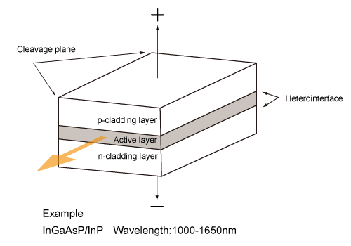
Fig.1.18 Structure of a typical semiconductor laser
For LD, the oscillation wavelength is tunable dependent on the type of compound semiconductor and the structure. LD can oscillate in the wide wavelength range from ultraviolet to near-infrared. LD is superior to other lasers in terms of size (compact), cost (cheap), and efficiency (~60%). Relatively low-output LD is variously used in our life for pick-up devices in CD (780nm), DVD (650-680nm), and blu-ray disc (400-410nm), laser printer (630-690nm), laser pointer, and optical communication (1.3~1.6µm). LD with an output of several W to several tenth W has been employed as excitation light sources of semiconductor pumping solid-state laser (808 and 914nm) and fiber laser (915, 975, 980, and 1480 nm). Recentely, LD in the blue (410nm) and green (512nm) have been developed a lot, and are being applied to a laser TV and a compact laser projector.
HIgh-power LD with several hundreds W to several kW is used for processing such as laser weld, and is called as direct LD. The direct LD has a bad beam quaility owing to its configuration, and is applicable to only limited cases. LD with several hundreds W has an array structure where a number (20~50) of high-power single emitter LD which are not mounted are one-dimensionally arranged in the range of around 1cm. This array is called as LD bar or LD array. Structure that a number of LD bar are stacked with very thin heat sink is called as LD stack. Generally, the number of stacking layers is 3~25, and the avarage output is several kW. The output of direct LD apparatus is reported to be 5kW at maximum.
4.3.1. Future generation
4.3.1.1. Surface emitting laser
The cleaved LD emits light from the edge face of semiconductor (edge face emitting laser), while some LD emits laser light orthogonally to the base. The latter is called as surface emitting laser or vertical cavity surface emitting laser (VCSEL). VCSEL was invented in 1977 by Iga, and the first oscillation was reported in 1979. VCSEL is low-cost since the cleavage is not necessary, and is used in laser printer, bar code, and mouse. The oscillation wavelengths are in the ranges of 850, 1310, and 1550nm. VCSEL of 850 nm range oscillation (AlGaAs type) is utilized for short-distance optical communication and fast LAN. Wiih VCSEL of 1070 nm range oscillation (InGaAs type active layer), a direct modulation operation at 25Gbps was reported in 2006 for data transmission of super computer. If surface emitting laser were available in the RGB, it could be applied to a new type of illumination and display.
4.3.1.2. Quantum dot laser
Quantum dot laser (QDL) utilizes quantum dot (suggested in 1982 by Arakawa and Sakaki), in which free electrons are confined in three-dimension by nanometer size semiconducting tiny crystal. QOL is expected as future generation optical communication laser because of the low consumption electric power, temperature independence, and fast modulability at 1310nm. Recently, QOL has been studied a lot in the world. Optical communication at 25Gbps has been demonstrated. 1.3µm laser oscilation on silicon substrate at room temperature has been also realized.
4.3.1.3. Quantum cascade laser
Quantum cascade laser (QCL) is a type of LD which operates at and over the wavelength of 2µm. QCL is a new type of LD employing intersubband transition, and has been eagerly studied since 1994 when J.Faist et al. from AT & T Inc. developed QCL. The oscillation wavelength at room temperature is in the range of 4µm~13µm. The CW output of several W is possible for QCL. However, because the wall-plug efficiency of QCL is relatively low compared with an usual LD, the thermal control is one of important factors for QCL. Applications of QCL are now considered in gas sensing, engine burning test, life science, and medical field.
4.4. Solid-state laser
Laser medium of solid-state laser is rare-earth-doped crystal or glass. Solid-state laser can be compact and high-power. In order to form the inverse population in solid-state laser, a good transmittance,
a good heat resistance, and a small temperature-dependency are required for a laser medium.
The typical solid-state laser is Nd:YAG laser, in which trivalent Nd ion, Nd3+, is doped with YAG (yttrium Aluminum garnet: Y3Al5O12) crystal. Solid-state laser is optically pumped. The pumping light source is mostly LD. Before the improvements of output power, efficiency, and lifetime of LD, noble gas flash lamp was used since it is a low-cost and high-power light source. However, in the flash lamp pumping method, the emission spectrum covers a broad range from UV to IR, therefore does not have a good consistency with absorption spectrum of laser medium, resulting in a large thermal burden on the laser medium. On the other hand, for LD, the emission spectrum is narrow, therefore it is possible to selectively excite a specific absorption transition in a medium, then a high absorption efficiency can be realized. Additinonally, because light emitted from LD is coherent, light can be tightly focused, then a high density pumping is possible.
Generally, a medium of solid-state laser has a rod shape and diode pumped solid state (DPSS) laser is pumped by a method as shown in Fig.1.19. Fig.1.19(a) represents the LD side-pumping method, while (b) shows the LD end-pumping method. For both of these methods, by inserting optical elements required in the resonator, an oscillating operation by Q-switching method or mode-locking method becomes possible. In a practical high-power solid-state laser, a cooling system or air-cooling or water-cooling is incorporated, and LD is often arranged in 3-D.
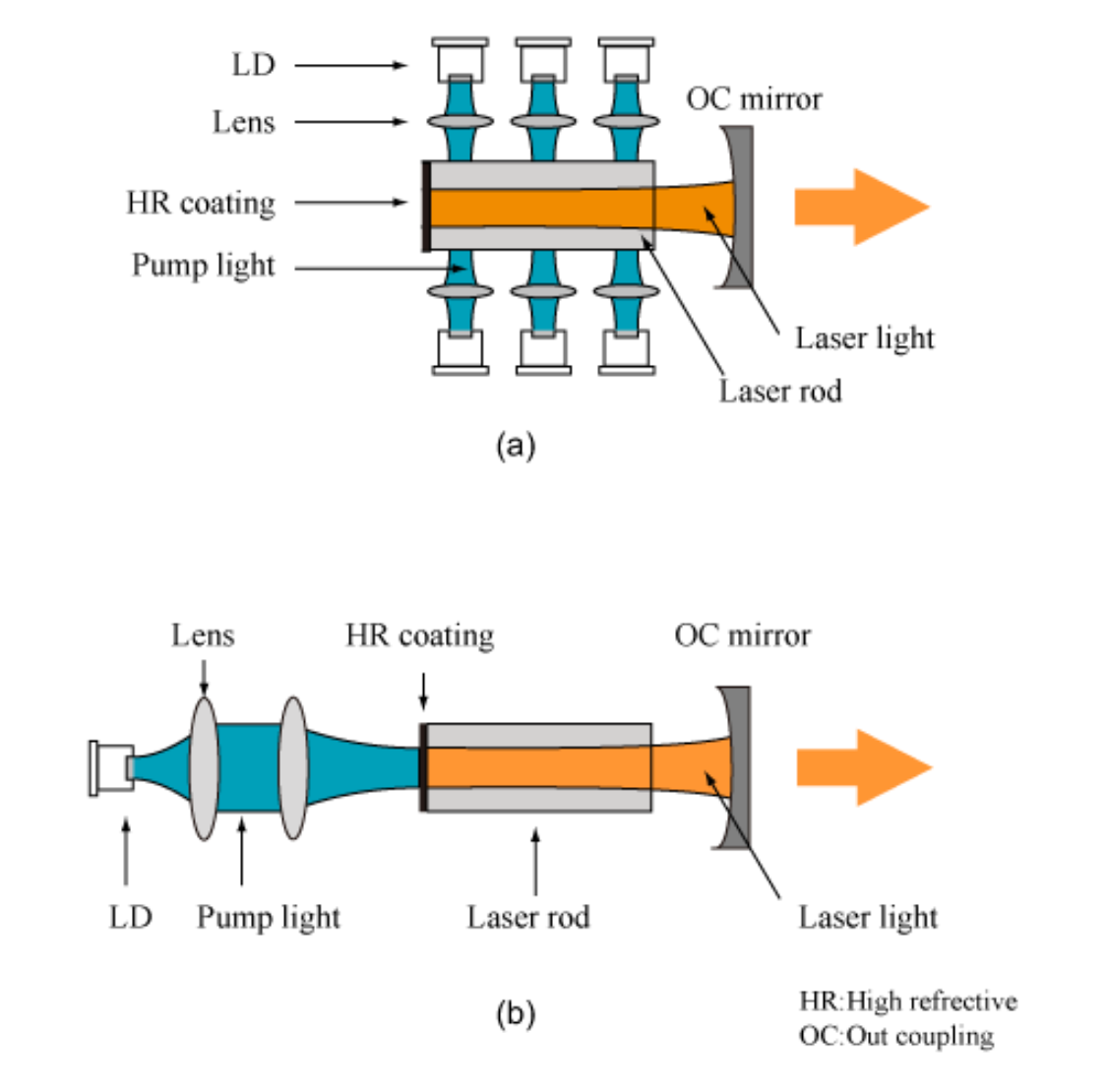
Fig.1.19 Solid-state laser pumping methods (a) the LD side-pumping method, (b) the LD end-pumping method
In the following text, we will briefly explain representative DPSS lasers including Nd:YAG laser, Yb:YAG laser, and titanium sapphire laser. Table 1.5 compares the crystal properties for these DPSS lasers.
Table 1.5 Comparison table of Nd:YAG, Yb:YAG and Ti:Sapphire crystal
| Crystal | Nd: YAG | Yb: YAG | Ti: Sapphire |
| Fluorescence life (ms) | 0.23 | 0.96 | 0.0032 |
| Induced Emission Cross Section (×10-20cm-1) | 20~30 | 2.1 | 30 |
| Fluorescence wavelength (nm) | 1064 | 1030 | 660-1100 |
| Absorption wavelength (nm) | 808 | 941 | 514~532 |
| Fluorescence bandwidth (FWHM) (nm) | 0.67 | ~10 | 440 |
| Absorption bandwidth (FWHM) (nm) | 1.9 | >10 | 200 |
| Excitation quantum efficiency | 0.76 | 0.91 | 0.55 |
| Saturated fluence (J/cm2) | 0.67 | 9.2 | 0.9 |
| Literature | 70)-73) | 74), 75) | 76), 77) |
4.4.1. Nd type laser
In Nd:YAG laser, trivalent Nd ion, Nd3+, is doped in YAG. Nd:YAG laser is the most common high-power solid-state laser. This is because Nd3+ has energy level structure for four-level model and because YAG crystal is so superior to other laser materials in term of the thermal conductivity.
The pumping wavelength and the oscillation wavelength of Nd:YAG laser are 808nm and 1064nm, respectively. Arranging a number of rod media in the axial direction of the resonatore enables several tenth kW CW oscillation. In fact, a number of companies has realized products of several kW Nd:YAG laser for weld of steel and aluminum. The output of a typical Nd:YAG laser is, however, at most several hundreds W. The typical repetition rate of Nd:YAG pulsed laser is in the range between several Hz and several kHz. At Q-switching operation, a high power pulse (several hundreds mJ) of a duration of 10ns~50ns has been generated.
The second harmonic generation (532nm), the third harmonic generation (355nm), and the fourth harmonic generation (266nm), all of which are generated via nonlinear optical effects, are frequently used. Nd:YLF (LiYF4)m Nd: YVO4, and Nd:glass are some of Nd types of DPSS laser other than Nd:YAG.
4.4.2. Yb type laser
In Yb:YAG laser, trivalent Yb ion, Yb3+, is doped in YAG crystal. Yb:YAG laser is different from previous both four-level laser such as Nd:YAG and three-level laser, but is quasi-three-level laser. In Yb:YAG laser, (1) the high quantum efficiency enables highly-efficient CW laser, (2) the long fluorescence lifetime is advantageous for the Q-switching method and the pulsed amplification, (3) the wide fluorescence spectrum enables picosecond or short pulse generation and amplification. Yb:YAG laser has a lot of advantages over Nd:YAG laser.
Fig.1.20 shows absorption cross-section and stimulated emission cross-section for Yb:YAG laser. Fig.1.20 indicates that the pumping wavelength (941nm) and the oscillation wavelength (1030nm) for Yb:YAG laser are close each other. Because of this, the pumping quantum efficiency of 91.4% is achieved, then the heating accompanying with the pumping is suppressed at 10% or so on (1/3 to 1/4 of Nd:YAG). Therefore, the thermal stress in the crystal is hard to accumulate, and the cooling is easy. Additionally, in Yb:YAG laser, because the energy loss by heat is low, the efficiency and output power is improved. In fact, by using Yb:YAG disk laser available in the market, an electric-optic conversion at an efficiency of around 20% was realized (electric-optic conversion efficiency for LD pumped Nd:YAG laser is around 10%).
In Yb:YAG crystal, Yb3+ (0.87Å), the dopant ion, and Y3+ (0.90Å) of YAG, the host material, have close ion radii (Nd3+ has about 1.5 times larger ion radius than Y3+). Therefore, Yb3+ can be doped at a high concentration (since concentration quenching hardly occurs), up to 100 at.%. The disadvantage of Yb:YAG laser is reabsorption loss (lower level loss), then is that high power pumping is necessary. In order to avoid these disadvantages, 1048nm fluorescence peak where reabsorption loss is relatively small is pumped.
Stimulated emission cross-section for Yb:YAG laser is approximately 2×10^2cm^2, which is one-order smaller than that of Nd:YAG laser. Since no parasitic oscillation occurs, great energy can be stored in a small volume. However, for extracting energy in pulsed operation, 10 times higher or more fluence is required compared with CW operation. In the case of pulsed amplification, optical damage can be an issue.
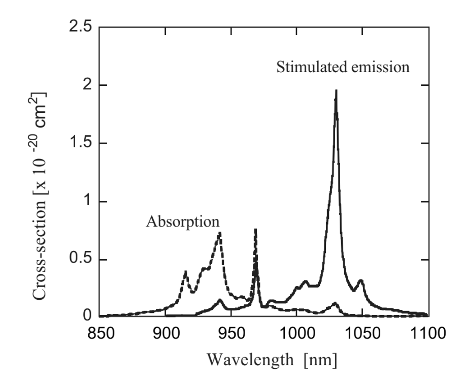
Fig.1.20 Absorption cross-section and stimulated emission cross-section for Yb:YAG
4.4.2.1. Quasi-three level model
A laser medium for quasi-three-level model satisfies E~kT in the four-level model shown in Fig.1.8. At low temperature, the medium is for the four-level model because of E< Yb:YAG laser is composed of two simple electronic levels, 2F7/2 and 2F5/2. Each level has sublevels: 4 sublevels for 2F7/2 level due to crystalline field and 3 sublevel for 2F5/2 due to the Stark devision. The laser operates by using these sublevels. 0cm-1 is the ground level, and 10327cm-1 is the laser upper level. Because the energy level structure is such a simple, excitation state absorption where ion excited to the upper level of 2F5/2 absorbs light, and up-conversion hardly occur. However, Energy difference among sublevels due to Stark shift is several hundreds cm-1 for both of 2F7/2 and 2F5/2. At room temperature, thermally excited ions are distributed to all of sublevels, which are laser lower levels, for the 2F7/2 level. Therefore, the inverse population is hardly formed. Ion in the laser lower level exhibits an effect of absorbing laser light. This effect is called as reabsorption or reabsorption loss of laser light. To overcome the reabsorption loss, the specialized cooling or the strong pumping was previously required. Nowaday, Yb:YAG laser is in common as disk laser, a kind of solid-state laser. In the following, the disk laser is briefly explained.(図1.21の文章なし)
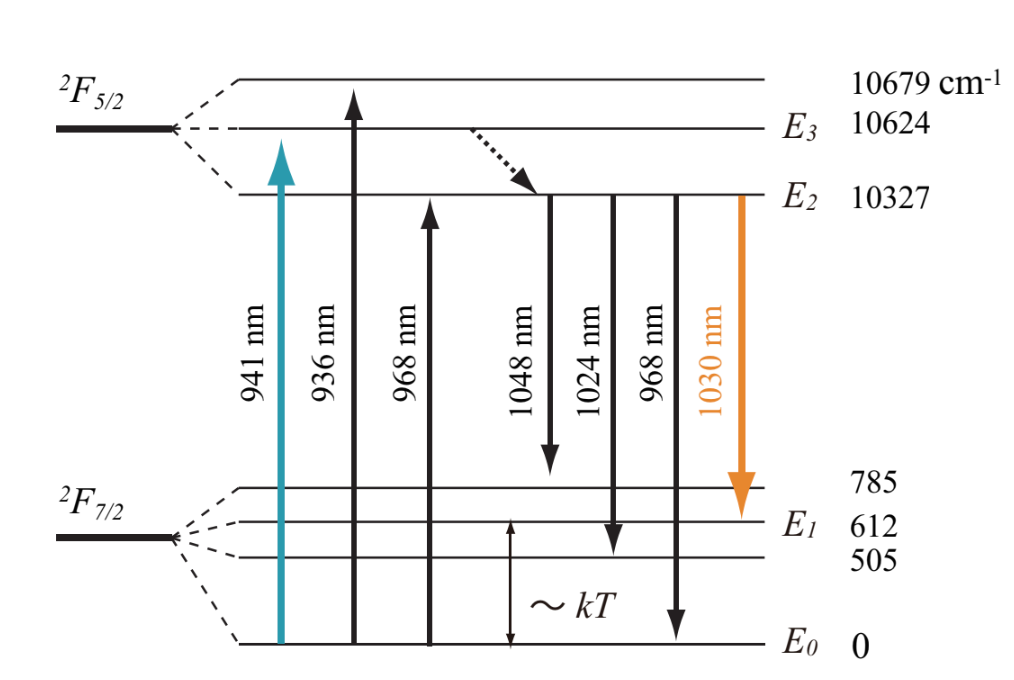
Fig.1.21 Energy level diagram of Yb:YAG laser
4.4.2.2. Disk laser
The disk laser was suggested by Adolf Giesen et al. from Stuttgart university in 1990s. For the disk laser, a very thin disk-like crystal (called as an active mirror) shown in Fig.1.22 is used as a laser medium. Because the heat emission performance can be improved by increasing [surface area/volume] portion, the disk laser is often compared with fiber laser. As a laser medium for the disk laser, Yb:YAG or Yb:YVO4 is used. A typical thickness of the disk-like crystal is 100~200µm, and the diameter is several mm. When the medium is fused with a cooling heat sink via indium, the heat generated from the laser medium disappears over the flat surface in one direction, and the temperature gradient in the laser crystal is almost uniform. Therefore, the thermal lensing effect is suppressed for the disk laser by one digit compared with the rod laser, then a stable and good beam quality is obtained.
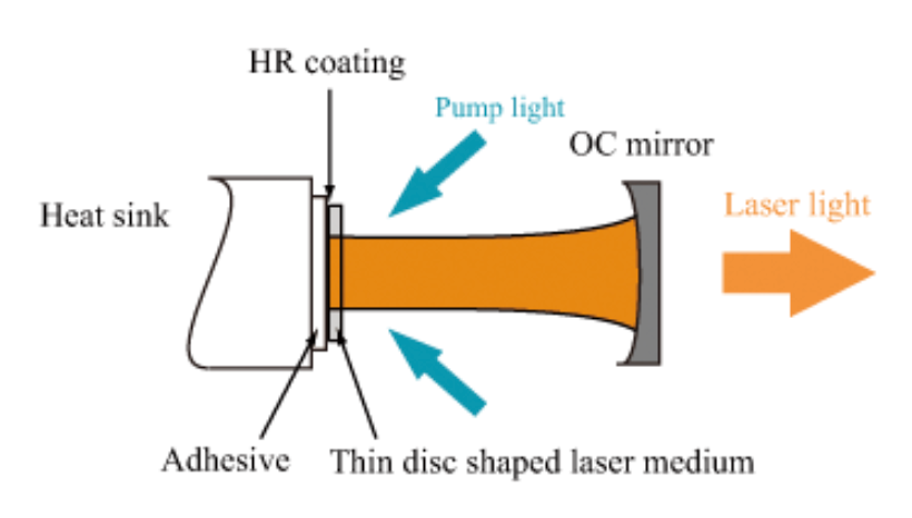
Fig.1.22 Configuration diagram of disk laser
The rear surface of disk is treated by total refection coating for both pumping and laser light, while the top surface is treated by anti-reflection coating for both pumping and laser light. Because of the light reflection at the rear surface of disk, the pumping light penetrates twice through the disk with once irradiation. However, because the disk is thin, an irradiation of pumping light yields a low absorption efficiency. In order to compensate the low efficiency, a parabolic mirror is arranged at the opposite side to the incident beam, and the pumping of 8 or 16 passes are performed until the disk completely absorbs the pumping light. Then, for one disk, singlemode oscillation can be obtained at 500W output, and multimode oscillation can be obtained at 4kW output. 16kW output disk laser which integrates a number of multimode disk lasers is currently available in the market.
Mode-locked disk laser has been also eagerly studied. High power laser with several tenth W output with a subpicosecond duration and high average power laser with 140W average output were reported. Femtosecond disk laser is also studied.
4.4.3. Ti:sapphire laser
Oscillation of titanium sapphire laser was first realized in 1982 by P.F.Moulton. Titanium sapphire (Ti:Al2O3 or Ti:Sapphire) crystal is synthesized by Ti3+ doping on sapphire crystal, which is also used as a base material for ruby laser (Cr:Al2O3 laser). Al2O3 is appropriate as a base material of high-repetition and high power laser since it has a good thermal conductivity. Instead of dye laser, Ti:Sapphire laser is widely used for a variety of research fields of femtosecond spectroscopy, nonlinear optics, white light generation, and terahertz generation.
Fig.1.23 shows an absorption spectrum and a fluorescence spectrum of Ti:Sapphire laser. Because the fluorescence spectrum of Al2O3 is very broad, Ti:Sapphire laser is tunable in the range of 660-1100nm by an insertion of a wavelength selection device in the resonator. By mode-locking, the pulse duration of 5.5fs has been realized. Nowadays, studies for a shorter duration is proceeded. For a typical Ti:Sapphire laser, the pulse duration is ~100fs, the repetition rate is 70~80MHz, and the average power is ~2.5W.
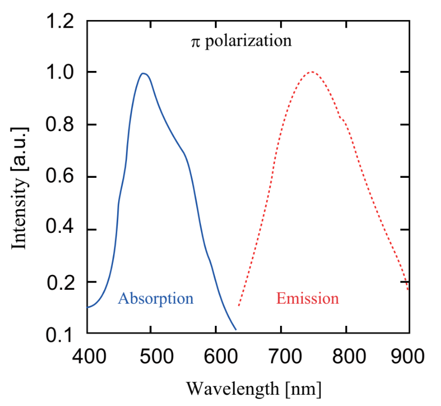
Fig.1.23 Absorption spectrum and a fluorescence spectrum of Ti:Sapphire
The absorption spectrum is in the green range (the maximum at 488nm), and the fluorescence lifetime is short and the stimulated emission cross-section is small. Therefore, intense pumping light with a good beam quality is necessary for laser oscillation. So, argon ion laser or a second harmonic generation component of Nd:YAG, Nd:YLF, or Nd:YVO4 laser is used for the pumping, but not LD. This is a cause of instability of Ti:Sapphire laser. Recently, a direct pumping using LD has been considered.
Cr:Forsterite laser using Cr:Forsterite crystal is a near-infrared ultrashort pulsed laser which oscillates in the same manner with Ti:Sapphire laser. Cr:Forsterite laser is available in the market. Cr:LiSAF laser and Cr:LiCAF laser are also available. These laser are pumped by InGaAlP type LD (670nm band).
4.4.3.1. Bulk-type mode-locking laser
A typical configuration of mode-locking titanium sapphire laser is Kerr-lens mode-locking (KLM) or self-mode-locking, both of which employs nonlinear optical effects, shown in Fig.1.24. As well as typical solid-state lasers, laser light is oscillated and amplified via input of the pumping light in the resonator. The intense part of amplified laser light converges via the Kerr-lens effect induced in the medium (Intense light changes a refractive index of medium, then the medium turns to be like a lens). The intense part of laser light is selected by a slit, subsequently only intense pulses stably exist in the resonator. This is a generation mechanim of the ultrashort pulses. A couple of prisms in the resonator are used for compensating pulse elongation by temporal Kerr-effect (self phase modulation) induced in the laser medium. Chirped mirror can be also used instead of the prisms. Recently, by using semiconductor saturable absorber mirror (SESAM) but not KLM, a mode-locked laser has been realized.
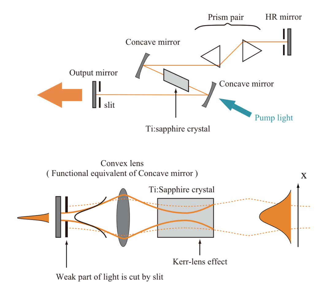
Fig.1.24 Kerr-lens mode-locking titanium sapphire laser
4.5. Fiber laser
For the bulk-type solid-state laser described above, a coupling between the pumping light and laser light is difficult, then a mode control is difficult. The output and the beam quality are lowered owing to an attachment of the grit and dust to mirrors and leses in the optical setup, and to an optical axis shift derived from thermal and mechanical changes influenced by the surrounding environments. In the high-power laser, thermal effects such as the thermal lensing effect and the thermal birefringence effect are remarkable, resulting in a drastic degradation of the beam quality. In order to avoid the thermal effects, colling systems with a high cooling efficiency, such as active mirror type or split disk type, have been suggested. However, these colling systems has a complex structure, and is not often used in industrial applications.
The fiber laser utilizes rare earth doped fiber as a laser medium. Although the fiber laser is one of solid-state lasers, the fiber laser and the bulk-type solid-state laser such as an Nd:YAG laser are, in general, separately discussed since the medium shapes are totally different. The fiber laser can be operated at both the CW and pulsed oscillations. The CW fiber laser is high-power, then is often employed for the ablation and the weld. The pulsed fiber laser is low-power, then is often used for the micro-processing and the marking.
Fig.1.25 represents a basic configuration of fiber laser. Fig.1.25(a) shows a resonator configuration for Fabri-Pelot fiber laser, in which only a laser gain medium is an optical fiber, integrated with a spatial coupling device. The configuratio shown in Fig.1.25(b) replaces mirrors in the configuration of Fig.1.25(a) by fiber Bragg gratings (FBGs). Fig.1.25(c) represents a ring-type fiber laser. Thus, constituent elemennts for the fiber laser are the same as the elements used in the bulk-type solid-state laser, but it is possible to reduce the number of elements by replacing the bulk-type resonator constituent elements by inline elements. For the previous bulk-type laser resonator, the alignment of resonator is complex, and the construction of laser oscillator requires sufficient experiences and construction time for the user. On the other hand, for the fiber laser, a modularized optical fiber (communication) technique can be used, therefore it is easy to construct the stable laser oscillator without special techniques.
As a fiber laser, erbium (Er) doped fiber laser for optical communcation range (1.5µm) was first practically used. In 1985, a technique for manufacturing a low-loss silica glass singlemode fiber was established by the modified vapor deposition (MVCD) method. In 1987, a low-noise Er-doped fiber amplifier (EDFA) applicable for the 1.54µm range where the loss of silica glass fiber is the smallest was developed. Then, the direct amplification of optical signal became possible without using the photoelectric conversion. The development of EDFA activated a market of the optical communication, diffused InGaAs-type LD and improved its performance, and rapidly brought forward the research and development of optical fiber laser amplifier.
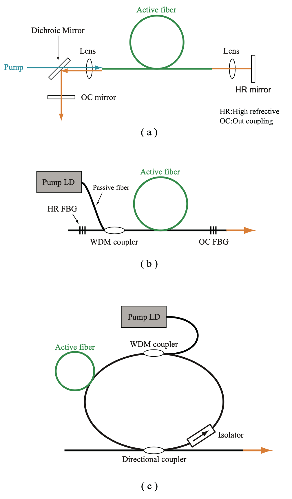
Fig.1.25 Basic configuration of fiber laser
As a high-power fiber laser used for applications other than the optical communication, the Nd doped fiber laser (Nd fiber laser) was first developed. In 1988, an Nd fiber laser with the clad pumping was developed and changed the previous idea of pumping (the core pumping was only possible previously). As a result, the output of CW fiber laser was dramatically incremented. In the clad pumping Nd fiber, the CW output of 100W in 1999 and 1kW in 2002 was realized. Recently, as a high-power laser with relatively higher performance compared to the Nd-doped medium, ytterbium doped fiber laser (Yb fiber laser) has been eagerly studied. Yb doped fiber laser oscillates in the range of 1030~1100nm. The CW output of 2kW in 2005, 6kW in 2008, and 10kW in 2009, and the multimode output of 50kW in 2009 were realized for Yb-doped singlemode fiber laser. The transition history of CW output of the Yb-doped singlemode fiber laser is shown in Fig.1.26.
Because the fiber laser has a very good beam quality, the fiber laser is becoming dominant in uses for industrial applications such as scission processing, marking, and remote weld. For the range of 2µm, thulium doped fiber laser (Tm fiber laser) has been recently studied. The Tm-doped fiber laser is now considered to be used for applications to medical devices and special processing since it operates in the eye-safe wavelength range.
The pulse duration of a typical ultrashort pulsed fiber laser is in the range of several ps ~ 100 fs, but a fiber laser with a pulse duration shorter than 100fs is also being studied. The fiber laser with 25fs pulse duration is commercially available. The femtosecond fiber laser is more compact and stable than the other types of femtosecond lasers, and is expected as an alternative to the titanium sapphire laser.
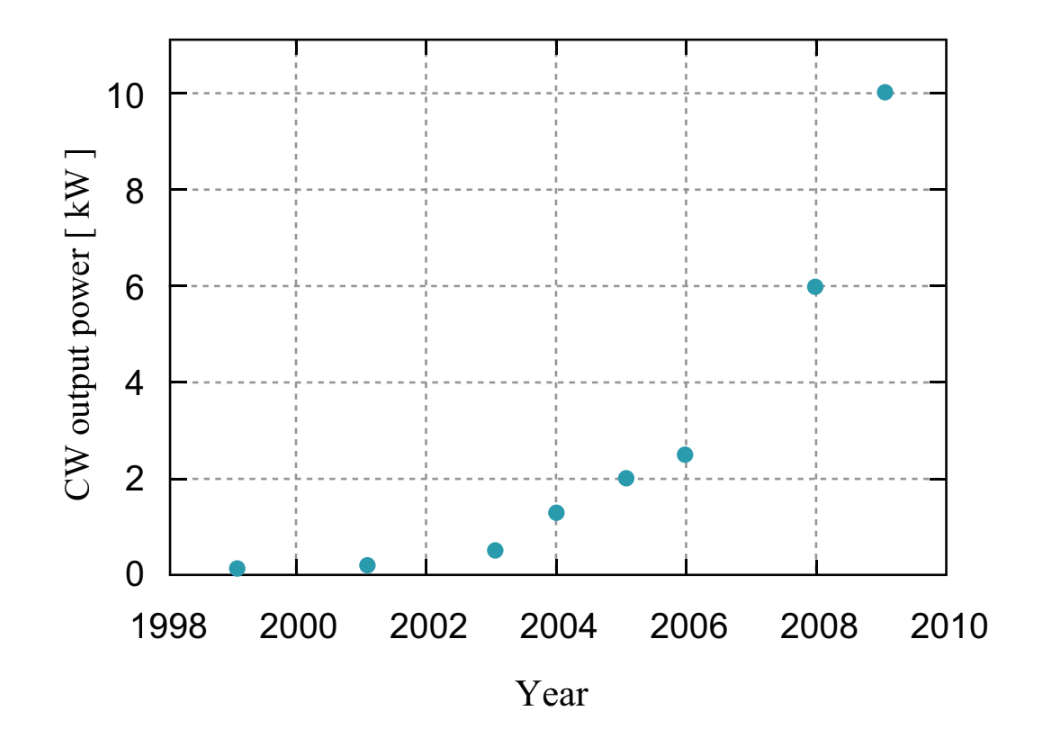
Fig.1.26 The transition history of CW output of the Yb-doped singlemode fiber laser
5. FIber laser characteristics
5.1. Compact and light
Optical fiber can be made compact and light since the fiber can be rolled up. Additionally, because the laser head can be small, a flexible system up is possible. Therefore, the setup cost can be saved and the setup position can be flexibly determined.
5.2. Maintenance free
For bulk-type high-power solid-state laser, since thermal effects, such as the thermal lensing effect and the thermal birefringence effect. are remarkable, the beam quality is dramatically lowered. Therefore, when a bulk-type solid-state laser is developed, a cooling system must be carefully designed. On the other hand, the cooling system for fiber laser with 100W or less is a simple air-cooling. This is because the fiber laser is superior in the heat releasing property since [surface area/volume] of an optical fiber which is used as a laser medium is fourth-order or more larger than that of a rod-type medium in the bulk-type solid-state laser. Fig.1.27 shows schmatics of radiation properties for rod-type solid-state laser, disk laser, and fiber laser.
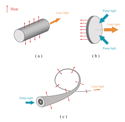
Fig.1.27 schematics of radiation properties for rod-type solid-state laser, disk laser, and fiber laser
5.3. Good beam quality
Laser light emitting from an optical fiber is easy to focus since the NA of fiber laser is relatively small. Therefore, the high-power density of output is realized, then high resolution processing is allowed. Furthermore, in implementing a fiber laser into a marking system, since small Galvano mirrors is available, a price reduction and a speeding up of the whole system is possible. In intergrating a singlemode fiber into the system constituion, the transverse mode can be almost perfectly unified.
5.4. Good lond-period stability
Because laser light is emitted from an optical fiber, the spatial fluctuation of laser beam is negligibly-small if the fiber is fixed. For all-fiber-type fiber laser where free-space optical setup is not included, thermal and mechanical effects caused by an attachment of grit and dust, and an surrounding environment are small since the all-fiber type fiber laser does not have any spatial optical device. Compared with CO2 laser, which is mostly used for laser processing applications, the fiber laser has both merits and demerits, but is superior in terms of short oscillation wavelengrth, good beam quality, and long focal depth. Therefore, the fiber laser can be used for processing an object put away from the focusing lens.
5.5. Wide gain width, high gain, high efficiency
Rare earth doped silica glass fiber, which is often used as a gain medium of fiber laser, is influenced by a complex crystalline field, and exhibits a broad level without micro-structure. Therefore, the rare earth doped silica glass fiber allows more wideband optical amplification than YAG crystal. In an optical fiber, even if a gain per unit length is small, a sufficient total gain is obained since the interaction length is long, Furthermore, because it is possible to confine the pumping light in the fiber, the highly efficient pumping is possible (optical-optical conversion efficiency:~70%, electric-optical conversion efficiency:~30%).
5.6. High-power
By serially or parallelly connecting modules, the amplification of output power is relatively easy. 50kW level super high-power CW fiber laser (transmission in fiber with the core diameter of 100µm ) has been already realized.
5.7. Long-distance propagation
Laser light emitted from the fiber laser can be efficiently coupled with a transmission fiber. By using the transmission fiber, it is possible to process an object put away from the laser body.
5.8. Nonlinear optical effect
In an optical fiber, because the core diameter is small and the interaction length is long, a nonlinear optical effect tends to be generated. Therefore, it is not appropriate for the high power pulsed operation, and may limit the characterisctics of laser. However, by using these properties, researches with a high novelty are eagerly performed.