DFB LASER DIODE
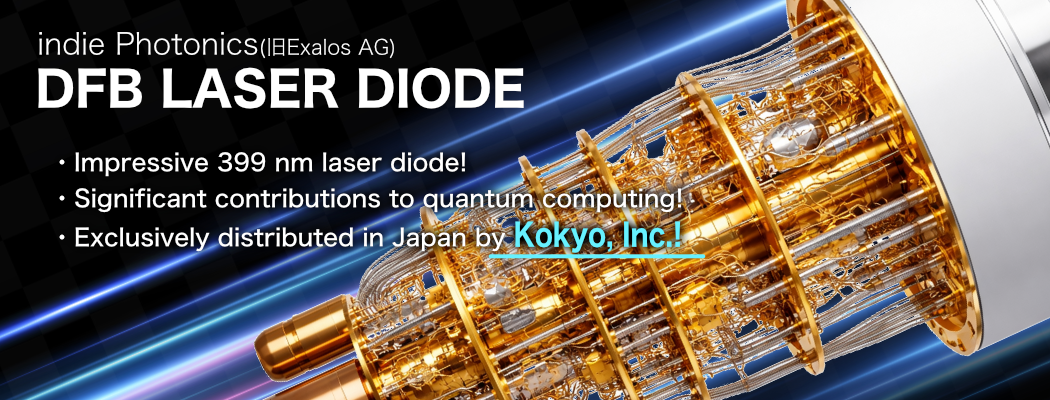
wavelength 399nm UV DFB LASER DIODE
ELA350028-00
↳ Key Highlights!
- Impressive 399 nm laser diode!
- Significant contributions to quantum computing!
- Exclusively distributed in Japan by Kokyo, Inc.!
Applications
- Atomic spectroscopy
- Raman
- Metrology
Light emission features
- Single longitudinal mode
- Single transverse mode
- Thermo-electrically tunable
- Linearly polarized
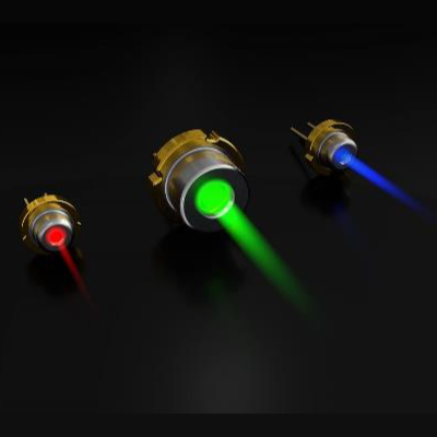
- Divergent free-space output
| Parameter | Symbol | Cond | Min | Max | Unit |
|---|---|---|---|---|---|
| Output power | P | 20 | mW | ||
| Forward current | IF | T = 25℃ | 90 | mA | |
| Reverse voltage | VR | -2 | V | ||
| Forward voltage | VF | 6 | V | ||
| Storage temperature | Tstg | -40 | 85 | ℃ |
| Parameter | Symbol | Min | Typ | Max | Unit |
|---|---|---|---|---|---|
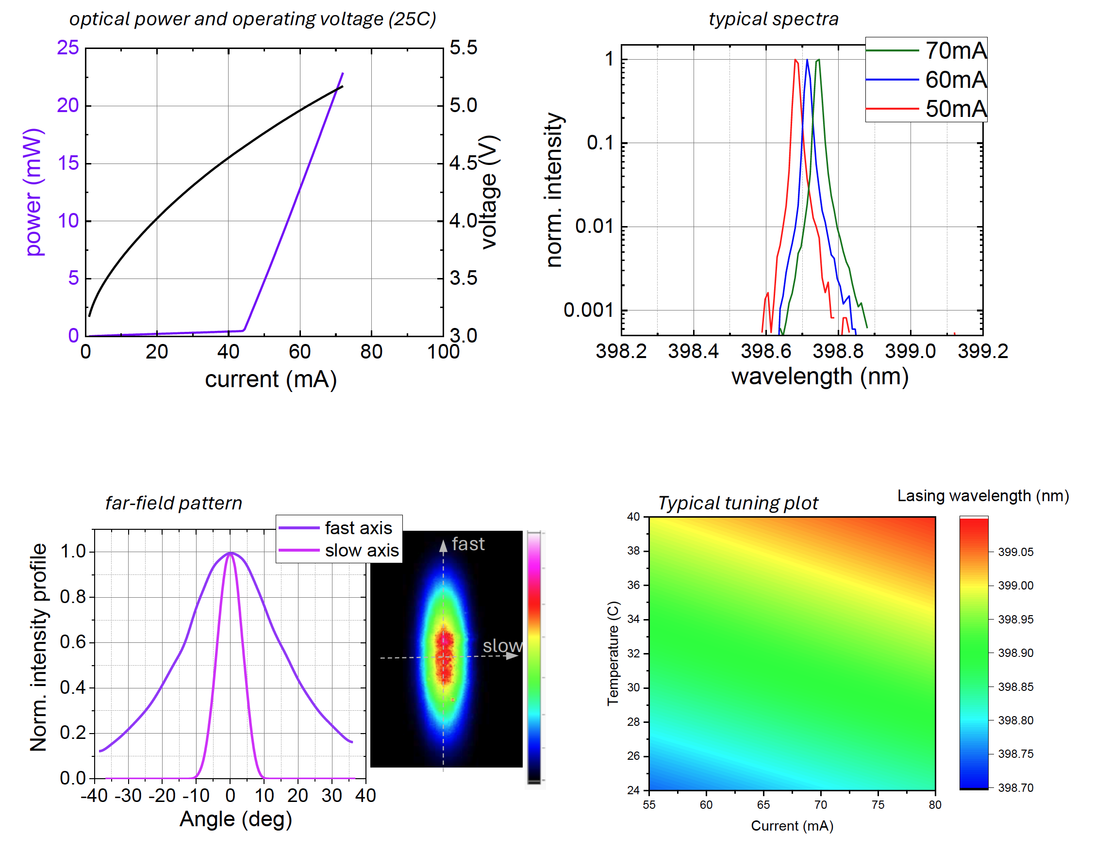
| Threshold | Ith | 40 | 60 | mA | |
| Slope efficiency | ηdif | 0.6 | 1 | 1.4 | W/A |
| Forward voltage | VF | 4.5 | 5.5 | V | |
| Lasing wavelength(1) | λ | 398.3 | 398.6 | 398.9 | nm |
| Laser linewidth (intrinsic) | Δλ | 1 | MHz | ||
| Thermal tuning(2) | λshift(T) | 15 | pm/K | ||
| Current tuning(2) | λshift(I) | 4 | pm/mA | ||
| PER (E // to SA) | re | 20 | dB | ||
| Farfield slow axis(FWHM) | Θ// | 6 | 9 | 12 | deg |
| Farfield fast axis(FWHM) | Θ⊥ | 25 | 30 | 35 | deg |
(1)wavelength is intended in vacuum at 25°C and for a power level of 10-20 mW.
(2)devices can be tuned to the 398.9 nm absorption line of Ytterbium. Depending on the exact wavelength of each DFB laser module at 25°C, the right case temperature for tuning to the Ytterbium line is expected to vary slightly, and within few tens of degrees C.
These characteristics are relative to a particular device under test.
Device to device variations may occur on a different set of samples.
To prevent potential chip damage inside the module or reduced package hermeticity, it’s advised that soldering time on the
pins should be less than 10 s and the temperature below 250 °C.
Heatsinking
The modules must be mounted on a heat sink with low thermal resistance (<0.5K /W) and a good module/heatsink joint must be ensured. Simple pressure/contact over a smooth heatsink surface can be enough in most cases. However, a better thermal joint may include the use of thermal fillers. Insufficient module heatsinking will result in a temperature rise and may lead to a reduction of the performance or even permanent damage or total failure.
Please note that the individual specifications of the devices are given at a case temperature Tcase of 25°C. Even though the modules can be operated under passive heatsinking, much better power stability and reliable operation will be achieved when using a temperature-controlled heatsinking scheme.
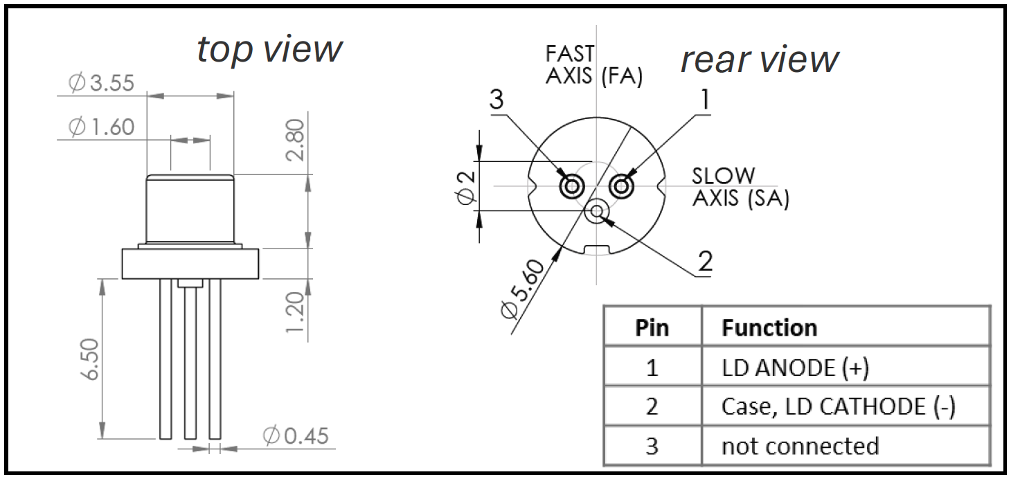
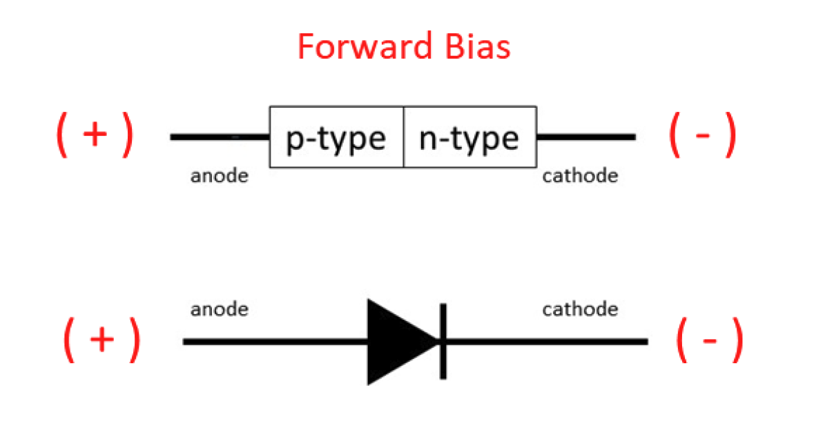
Electrical Connections to LDs
LDs are pn junctions which need to be driven in forward bias. The p-side (LD anode) must have a positive voltage with respect to the n-side (LD cathode). Although the LD is capable of withstanding a reverse bias, this is not the correct operating mode and should be avoided.
*Caution:Always ensure driver circuits are connected with the correct polarity.
Positive polarity must be connected to the LD anode. Negative polarity must be connected to the LD cathode.
Drive conditions
pn junctions in forward bias are very sensitive to voltage. Small voltage changes can give rise to high current changes and it is very easy to exceed absolute maximum current and/or output power ratings if the LD is driven with a controlled constant voltage source.
*Caution:The absolute maximum ratings reported in the data sheets must be carefully observed. Any value exceeding the specified parameters should be avoided, otherwise permanent damage may result. Independent of operating temperature, never exceed maximum allowed LD current, voltage or output power.
EXALOS offers driver boards designed specifically to operate LDs. Please contact EXALOS to discuss these products.
Alternatively, most 3rd party drivers designed for semiconductor lasers will work with EXALOS LDs. Always take great care to ensure that 3rd party or custom designed circuits match the required maximum drive currents for the purchased products and have appropriate protections against electrostatic discharge or fast current/voltage transients.
*Caution:モIt is strongly advised that the modules are driven with a current source. Constant controlled voltage mode exposes the module to the risk of exceeding the maximum current and output power limits. Take all precautions needed if voltage drive mode is strictly required (e.g. start operation at ½ of max. voltage ratings, then increase voltage in steps < 50mV while carefully monitoring the drive current).
Electrostatic Discharge (ESD) and Surge Current
LDs are sensitive to electrostatic shock/discharge. Ensure you are working in an ESD certified zone with appropriate ESD protection in place before you handle the modules. Tools such as soldering irons used during assembly must be appropriately protected against ESD.
Surge current or over current in the forward or reverse direction may permanently damage the diode. Use only laser-diode power supplies or constant current power supplies that can guarantee controlled current levels and prevent the LD to be overdriven even for very short periods of time. Make sure that all the wiring and electrical connections around the module are stable and functional.